One of the major features of interest in the Park Museum at Longmire
and in the Community Building at Paradise is the large relief model of
this park which is on display at each of those places. Both of these
models are identical, having been cast from the same mold. Because they
are accurate and faithful to detail, the park visitor is thus able to
view "The Mountain" in much the same manner as if he were flying over
the actual park in an airplane. This interest has resulted in many
questions regarding the manner of preparing such a model. The great
majority of these questions are prompted by more than idle curiosity,
and we take this opportunity to outline, in general, the steps in the
process.
Building a relief model requires considerable hard work, careful
application to detail, a lot of patience and a lot of time. Anyone
contemplating such a project should first resign himself to those facts,
otherwise the completed model - if it ever is completed - will not be
satisfactory. The character of the completed model will also be largely
determined by careful planning of all details (size, horizontal scale,
vertical scale, etc.) before a bit of material is purchased or a start
on the actual work is made. And now for the outline of the process.
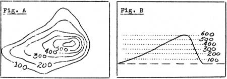
(1) A good topographic map of the region to be modeled is, of course,
necessary. This map serves as the pattern. The numerous wavy lines give
us a picture of the region's topography. Each wavy line (contour line)
connects points of equal elevation. Where these lines are far apart a
gradual slope is indicated; where they are close together a steep slope
would be found. (Fig. A and Fig. B illustrate the principle of the
topographic or contour map - a small hill serving as an example. In Fig.
A. the contours, connecting points of equal elevation on this hill, are
shown. The vertical distance between them is 100 ft. and this is known
as the contour interval. There is a gradual slope on the left and
a steeper slope on the right. In Fig. B. we see a cross section of this
hill with dotted lines indicating the position of the contours on the
mapped area of Fig. A.)
(2) The foundation of the model is built up of layers of cardboard.
The thickness of each cardboard layer indicates the contour interval of
the map - a layer, in miniature, of the earth. The wavy pattern of each
contour is first traced upon a sheet of cardboard, then cut out. In
order to simplify this description we will assume that the model to be
made is to be of the same size as the map. (If it is desired to enlarge
the model, lantern slides of the map are first made. These lantern
slides are projected upon a wall, by means of a sterioptican, to the
desired size and the contours traced, as described below, from the
projected image.)
As each is traced and cut it is placed upon those that have gone
before and tacked or glued down until the foundation is completed. It
will then have the appearance of an oriental terraced farm. Because each
thickness of cardboard indicates the map's contour interval the vertical
scale of the model must be given careful consideration for it determines
the thickness of the cardboard that will be used. If the cardboard is
too thick the hills will be too high and the valleys too narrow and if
it is too thin the reverse will be true. One may compute the thickness
of the cardboard necessary by dividing the horizontal scale of the map
by its contour interval. (If one inch equals 1000 feet on your map and
the contour interval is 25 ft. the cardboard to be used should be one
fortieth of an inch thick. If the contour interval is 50 ft. the
thickness of cardboard should be one twentieth of an inch, etc.) By
computing the vertical scale in this manner we will build a model in
which the horizontal and vertical scale are the same - the topography of
the model will be an exact miniature of the actual area. However many
relief models have the vertical scale exaggerated. This is particularly
true of those dealing with comparative flat regions where topographic
differences are not of an abrupt enough character to make them stand out
in the model. Exaggeration in such a case may be justified for then the
hills and valleys of the model appear to the eye more nearly as they
actually seem to us as we view them from the ground level. For areas of
rugged topography it is not necessary to exaggerate the vertical scale
and the tendency today in the building of such models is to make the
vertical and horizontal scale the same.
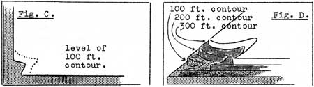
(3) In starting the foundation first locate on the map the contour of
lowest elevation. This should be traced upon the first sheet of
cardboard and the resulting pattern cut out and placed upon a suitable
base which has already been provided. The first cut-out will usually be
the outline of the map with a small notch, or notches, along the edge.
(In Fig. C. the shaded portion indicates the base of the foundation and
the heavy line a portion of the lowest contour which had been traced,
cut out and glued or tacked to the base. The dotted line is a portion of
the next highest contour which has been sketched in to serve as a guide
in placing the next thickness of cardboard. Fig. D. is a side view of
the same except that the second and third thicknesses of cardboard have
been laid on. The legend in each case is the same.) As each contour is
traced it is well to trace the next highest one to serve as a guide in
placing the next cardboard layer. Cutting is done with a jig-saw,
cut-awl or some similar instrument capable of doing accurate work. As
each contour is traced, cut and tacked down, the foundation will
gradually take form. The large cut outs break up into smaller units and
individual hills and valleys appear. When the foundation is completed it
will be composed of cardboard terraces which are in reality the contour
intervals of the earth, as indicated by the map, in miniature and to
scale.
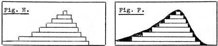
(4) Upon this foundation plastic clay is worked into the terraces
until the step-like effect is obliterated. This should be done very
carefully; applied just thick enough to cover the edges of the layers
(See Fig. E. and Fig. F.). Work in all topographical details with the
fingers and with modeling tools until the model is as finished and
faithful a presentation of the area as it is possible to be. When this
is done you are ready for casting.
(5) We first cast the "negative" - a replica of the model upside
down. Before casting the model experiment with plaster of paris by
casting small objects such as irregular gobs of plastic clay, etc.,
until you get the "feel" of how plaster of paris works. The clay model
is now greased or soaped (lather it as in shaving) to prevent the
plaster from sticking to it and sides are built up to prevent the
plaster from running beyond the models bounds. A large bucket of plaster
is mixed until it has a "soupy"" consistency. Ladel this "soup" on the
model until a thin layer covers it entirely. Now quickly dip strips and
squares of burlap (provided before hand and made ready to use) into the
plaster and lay them, dripping, upon the model. They will merge with the
thin layer of plaster which was ladeled on and, as they are placed so
that they overlap, will give strength to the cast when hard. Another
layer of plaster is laid on and another layer of plaster-soaked burlap
follows. (It may also be necessary to reinforce a large cast with wooden
or metal rods set in the soft plaster before the last burlap layer) The
plaster is now smoothed out and the entire cast allowed to set. When
sufficiently hard the sides are taken away and it is gently worked at
the edges with the fingers until the negative pulls away from the clay
model. A little touching up may be necessary, then the negative is
allowed to dry following which it is shellacked. We are now ready to
cast the "positive" - an exact replica of the clay model.
(6) Casting the positive is quite similar to the method used in
casting the negative. The negative cast is first greased to prevent
sticking, the thin plaster is ladeled on followed by layers of
plaster-soaked burlap until a shell of sufficient thickness is built up.
It is then allowed to set and the two sections worked apart. Touching up
follows and the positive is then shellacked and made ready for painting.
If your negative was a good strong one, any number of positive casts may
be made from it. Very large models are cast in sections (as in the case
of the Mount Rainier National Park relief model) and fitted together
like a jig-saw puzzle.
(7) Painting in the various colors to indicate barren rocky areas,
timbered sections, roads, trails, etc., follows. When this is done the
model is complete and is ready to be installed upon some suitable table
or hung in a suitable place on the wall.
C. Frank Brockman,
Park Naturalist.