|
Geological Survey Circular 838
Guides to Some Volcanic Terrances in Washington, Idaho, Oregon, and Northern California
|
A FIELD TRIP TO THE MAAR VOLCANOES OF THE
FORT ROCK - CHRISTMAS LAKE VALLEY BASIN, OREGON
G. H. Heiken, Geosciences Division, Los Alamos
Scientific Laboratory, Los Alamos, NM 87545
R. V. Fisher, Dept. of Geology, University of
California, Santa Barbara, CA 93106
N. V. Peterson, State of Oregon, Dept. of Geology and
Mineral Industries, Grants Pass, OR 97526
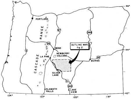
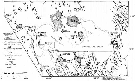
The Fort Rock - Christmas Lake Valley basin is a
former lake basin that existed from late Pliocene through late
Pleistocene time. The basin is about 64 km long and 40 km wide (Fig. 1).
Eruptions of basaltic magma occurred along faults that trend diagonally
across the basin and adjacent highland, forming maar volcanoes within
and on lake margins and forming cinder cones with flows beyond the lake
margins (Peterson and Groh, 1963; Heiken, 1971).
|
|
Figure 1: Location map.
|
The purpose of this field trip is to visit several of
the maars and a maar complex in and near the basin.
Road Log: (cumulative distance, in miles;
stop-to-stop mileages are in parentheses)
(Fig. 2).
|
|
Figure 2: Map of Fort Rock - Christmas Lake Valley Basin,
showing route of field trip. (click on image for an enlargement in a new window)
|
| MILES |
|
| 0.0 |
La Pine Junction intersection of Oregon State Highways 97 and 31.
Proceed down Highway 31, to the southeast. |
| (1.0) |
|
| 1.0 |
Large meadow; good view of Newberry Volcano to left
(north). |
| (1.9) |
|
| 2.9 |
Railroad crossing; as is typical of the area between
La Pine Junction and Fort Rock Valley, the surface (except for steepest
slopes) is mantled with Mazama pumice from Crater Lake. |
| (7.1) |
|
| 10.0 |
Bend in road; Moffitt Butte tuff ring is straight
ahead. |
| (0.3) |
|
| 10.3 |
Moffitt Butte is on left; its base is about 50 n east
of road in the woods.
Moffitt Butte
Moffitt Butte is a dissected tuff ring, 1400 m in diameter and 120 m
high. It is a prominent topographic feature, but is obscured by the
forest from the road. Although not associated with a lake basin, as is
the case for Big Hole and Hole-in-the-ground, Moffitt
Butte is a tuff ring composed of hyaloclastic tuffs. Rising magma may
have encountered permeable aquifers beneath the cone. A line of tuff
rings between here and the Fort Rock Basin are along a topographic low
between Fort Rock and the La Pine basins.
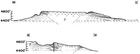
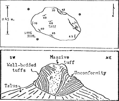
The crater floor of Moffitt Butte is about 80 m above the surrounding
plain. A parasitic vent, and small tuff ring, 510 m in diameter, is
located on its southwestern flank. The deposits consist of sideromelane
lapilli-tuff in graded and ungraded beds, 3 to 30 cm thick. Near
the main ring crest is an unconformity dipping 20° into the crater
that truncates beds dipping outward at 35° (Fig. 3). Rocks above the
unconformity consist of a 1 m thick bed of angular basalt blocks and 18
m of very well-bedded lapilli-tuff.
|
|
Figure 3: Cross-sections through Moffitt Butte, Klamath County
Oregon. The upper cross section is through the main body of the tuff
ring. The lower cross-section is through a parasitic vent on the
southwest flank of the ring; the lava-filled crater is close to the
highway. (click on image for an enlargement in a new window)
|
The crater of the parasite vent is filled with lava that issued from a
dike on its northwest edge. |
| (2.8) |
|
| 13.1 |
Road cut through pressure ridge or large tumuli in a basalt flow. This is
typical of many road cuts between here and Fort Rock Valley; basalt flows are from
vents on the southern flank of the Newberry Volcano; overlain by Mazama pumice. |
| (1.5) |
|
| 14.6 |
Junction of State Highway 31 with Rock Creek Road (gravel). Exposed in
road cut south of highway are remnants of an unnamed tuff ring (Ridge
28 of Peterson and Groh, 1963); gray to orangish-brown (partly
palagonitized), well-bedded hyaloclastites. Most units contain
accretionary lapilli. |
| (5.0) |
|
| 19.6 |
Junction, State Highway 31, Big Hole Road; turn off State Highway 31 to
right (south) to enter Big Hole (not included in the overall mileage).
Big Hole
A gravel road from this junction goes into the crater
of Big Hole, a circular, 1820 m diameter maar crater. Deposits of the
tuff ring are 24 to 30 m thick at the crest and extend 1800 to 2500 m
beyond the crater rim. The deposits are thickest on the northeast side,
along Highway 31 (Big Hole Butte).
The tuff ring is composed of moderate- to
well-bedded sideromelane lapilli-tuff and tuff breccia, in
beds 5 cm to a meter thick. The tuff-breccia beds include
porphyritic basalt blocks up to 2.5 m in diameter; there are abundant
bedding plane sags caused by impact of these blocks into once
water-saturated ash beds during the eruption. Best exposures of
these deposits are along gullies on the eastern rim of the maar.
Convolute bedding within the rim deposits is well exposed along the east
rim (Fig. 4).

|
|
Figure 4: Maar deposits, east rim of Big Hole. Well-bedded
tuffs and lapilli-tuffs are characteristic of the maar volcanoes
of this region. Convolute bedding is well displayed in places;
it is caused by decollement-like movement of cohesive tuff down
the flank of the tuff ring.
|
Within the crater is a 152 m-wide ledge that
appears to be the top of a large block that slumped into the crater,
possibly during the eruption. Collapse into the crater of such large
blocks would explain the large volume of the crater and small percentage
of xenoliths within the ejecta. |
| (0.6) |
|
| 20.2 |
On the right are well-bedded hyaloclastic tuff deposits of Big Hole
tuff ring. Deposits are thicker on the northeast rim, probably caused by prevailing
winds from the southwest during the eruption. The thicker deposit is called
Big Hole Butte, although it is not a separate structure or vent. |
| (0.4) |
|
| 20.6 |
Good exposure of Big Hole tuffs on right side of
Highway 31. |
| (4.5) |
|
| 25.1 |
Junction of State Highway 31 with the road to
Hole-in-the-ground (HIG) (Proceed along Boundary Road,
#245). The side trip to HIG will not be included in the overall mileage.
Forest Road 245 is gravel; follow signs for 2.8 miles (one left turn and
one right turn to the west rim and to HIG overlook).
Hole-in-the-ground
Hole-in-the-ground is described by
Peterson and Groh (1961, 1963) and by Lorenz (1971). Lorenz's (1971)
abstract is as follows:
"Hole-in-the-Ground is a volcanic
explosion crater or maar located in Central Oregon on the edge of Fort
Rock basin. At the time the crater was formed between 13,500 and 18,000
years ago a lake occupied most of the basin and the site of the eruption
was close to the water level near the shore. The crater is now 112 to
156 m below the original ground level and is surrounded by a rim that
rises another 35 to 65 m higher.
The volume of the crater below the original surface
is only 60 percent of the volume of the ejecta. The latter contains only
10 percent juvenile basaltic material, mainly sideromelane produced by
rapid quenching of the lava. Most of the ejected material is fine
grained, but some of the blocks of older rocks reach dimensions of 8
m. The largest blocks are concentrated in four
horizons and reached distances of 3.7 km from the center of the crater.
Accretionary lapilli, impact sags, and vesiculated tuffs are well
developed.
The crater was formed in a few days or weeks by a
series of explosions that were triggered when basaltic magma rose along
a northwest-trending fissure and came into contact with abundant
ground water at a depth of 300 to 500 m below the surface. After the
initial explosion, repeated slumping and subsidence along a ring-fault
led to intermittent closures of the vent, changes in the supply of
ground water, and repeated accumulations of pressure in the pipe. Four
major explosive events resulted from pressures of over 500 bars in the
orifice of the vent. Ejection velocities during these periods reached
200 meters per second. The corresponding pressures
and velocities during intervening, less violent stages were in the
range of 200 to 250 bars and about 130 meters per second.
The kinetic energy released during the most violent eruptions was
approximately 9 x 10²⁰ ergs and the seismic events that must
have accompanied these explosions had a magnitude of about 5. Ejecta 10
centimeters in size were thrown to heights of 2 to 3 kilometers and the
eruption cloud may have reached 5 kilometers or more. The axis of
eruption was slightly inclined toward the southeast; the form of the
vent seems to have had a more important influence than wind. Base surges
that accompanied some of the explosions left deposits of vesiculated
tuff.
The total energy derived from the basaltic magma was of the order of 5.7
x 1023 ergs. Most of this energy went into heating of ground water and
the enclosing country rocks; only a small part, possibly a tenth was
released by expansion and vaporization of the water and mechanical
processes, such as crushing, acceleration and ejection of debris.
Geophysical measurements indicate a domical intrusion below the
crater floor and extending upward as a ring dike around the margins
of the crater."

|
|
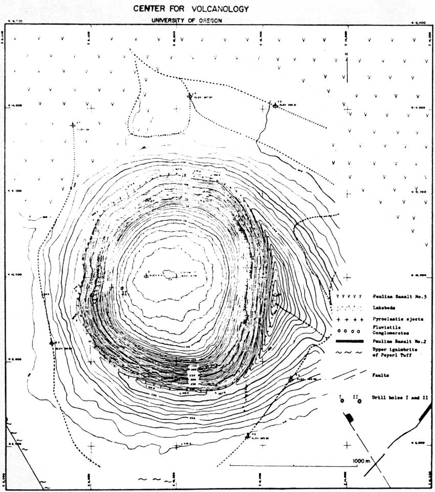
Figure 5: Topographic and geologic map of Hole-in-the-Ground.
Contour interval is ten feet. Field control by J. W. Hawthorne.
(click on image for an enlargement in a new window)
|

|
|
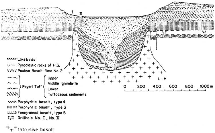
Figure 6: Geologic section through
Hole-in-the-Ground based on surface exposures, drill
holes and geophysical data. Interpretation by Lorenz (1971).
(click on image for an enlargement in a new window)
|
Return to State Highway 31. |
| (1.7) |
|
| 26.8 |
Picnic grounds on right. |
|
|
| 26 to 28.2 |
Section (top to bottom) through (1) basalt flow (from
flanks of Newberry Volcano?) and (2) Peyerl Tuff; a section consisting
of 4.0 m.y. old pyroclastic flows and tuffaceous sediments. The section
is exposed along Highway 31 in road cuts. If you stop, please leave your
auto at the top of the hill in the picnic grounds and stay on the edge
of the road; there are numerous fast-moving logging trucks on this
highway! |
| (0.9) |
|
| 29.1 |
Junction, Oregon State Highway 31 and Fort Rock Road.
Turn left (east) on Fort Rock road. Before reaching the lake basin floor, the road crosses
several north-south trending horsts and grabens
that cut through a section consisting of the Peyerl Tuff and Pliocene
(?) age basalt flows. On the left (north) of Fort Rock road along an
east-west line to Fort Rock are the remnants of four deeply eroded
basaltic vents. Only small remnants of lava lakes remain, but most are
surrounded by aprons of rounded cobbles and pebbles consisting of
palagonitized hyaloclastic tuffs. The vent closest to Fort Rock (Beggars
Heel) has a cave where some of the oldest man-made artifacts in
Oregon were found. |
| (6.4) |
|
| 35.5 |
Downtown Fort Rock and intersection with Fort Rock
State Park Road (follow signs). |
| (0.1) |
|
| 35.6 |
Turn left to Fort Rock State Park (if you stay on
this road and follow the signs, you can reach
Hole-in-the-Ground from the east side). |
| (0.5) |
|
| 36.1 |
Fort Rock State Park
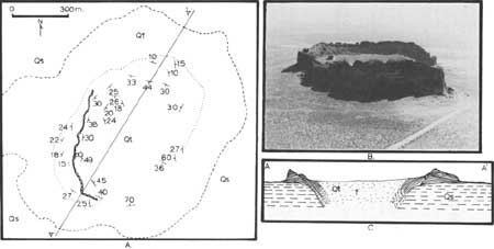
Fort Rock
Fort Rock, with its spectacular wave-cut cliffs,
is an isolated maar volcano within a monotonous, flat lake basin
(Peterson and Groh, 1963). The wave-cut remnant is 1360 m in
diameter and 60 m high, and the present crater floor is 6 to 12 m above
the floor of the lake basin. The south rim has been breached by waves of
the former lake, providing easy access to the crater. A wave-cut
terrace occurs 20 m above the floor of Fort Rock Valley (Fig. 7).
|
|
Figure 7: Fort Rock tuff ring. A. MAP Qs - Pleistocene lake sediments,
mostly diatomites. Qt - tuffs, lapilli-tuffs and tuff breccias. Scalloped
line is an unconformity. Dotted line is the cliff edge. B. Oblique
aerial photograph, from the southwest. C. Cross-section. (click on image
for an enlargement in a new window)
|
The maar is composed of orange-brown
lapilli-tuff in beds of 1 cm to 1 m thick that can be traced from
within the crater to the outer flanks. Graded beds with accretionary
lapilli are common.
Inward-dipping beds are parallel to the crater
walls (Fig. 7) and suggest that the crater is funnel shaped; the
innermost beds dip inward at angles of 20 to 70 degrees. On the west
side of Fort Rock is a distinct angular unconformity where the deposits,
truncated by slumping into the crater, are plastered with younger beds.
These younger beds are part of a continuous pyroclastic sequence on the
outer flanks. An incipient slump is visible on the east flank where the
sequence is in-place with quaquaversal dips away from the rim
crest; fracture planes associated with the slump, dip inward at 40
degrees, the same angle as the surface of the unconformity on the
opposite side of the crater.
Fort Rock is typical of most of the smaller, isolated
maars of the Fort Rock-Christmas Lake Valley basin, such as Table
Mountain, Flat Top, Lost Forest, Green Mountain SW and Green Mountain S
(Fig. 2). |
| (7.00) |
|
| 43.1 |
Return to junction of Fort Rock Road and Highway 31
and turn left (south), down Highway 31 toward Silver Lake.
An alternate route, from the center of
downtown Fort Rock, is south along Lake County Road 513. This is a
gravel road that is a short-cut to Silver Lake, but the bridges
will not support heavy trucks or buses. If you take this alternate route
of 16.5 miles, you will go between a north-south trending normal
fault (west) and the Connley Hills (east). As you leave the lake basin,
near junction with County Road 510-C you will see the northern end
of the Connley Hills, a line of domes of intermediate composition.
Remnants of a small maar are plastered onto the northernmost dome, near the
former lake shoreline. South of the Connley Hills is Hayes Butte, a
basaltic shield. These volcanoes stood as an island in the lake that was
present here during late Pliocene-Pleistocene time.
To the west, several broad, older (Pliocene) maar
volcanoes are exposed in a low ridge, partly buried by basalt flows, a
gravel road to the west (turn right, 5.3 miles south of the town of Fort
Rock) crosses one of these maars. It is on private land, however. Please
ask for permission to enter before doing so.
After crossing a small divide, you will enter Paulina
Marsh; no outcrops until you reach the intersection with Highway 31 near
Silver Lake. |
| (0.4) |
|
| 43.5 |
Road cut (Highway 31); park at base or top of road
cut. Be careful; stay on the side of the road. There are good exposures
of part of the Peyerl Tuff, a sequence of pyroclastic flows and
interbedded sediments, as much as 150 m thick, that crops out along the
west side of Fort Rock Valley. Radiometric ages of 4.47±0.84 and
3.35±0.44 m.y. were determined for several of
the pyroclastic flows (MacLeod et al., 1976). The source for these
pyroclastic units appears to be a 7 to 10 km wide caldera near Wart
Peak, that is about 15 km WSW of this stop. |
| (3.1) |
|
| 46.6 |
Junction, Highway 31 and Wickiup Springs
- Stains Well Road. The ridge on the horizon to the west is
near the east rim of the Wart Peak Caldera, identified by N. MacLeod.
Due south is a cinder cone of late Pliocene(?) age.
On the east side of the road is a poorly exposed
Pliocene(?) maar, the Wastina Maar of Peterson and Groh (1963). |
| (19.4) |
|
| 56.0 |
Straight ahead (south) is Hager Mountain, a 5.9 m.y.
old silicic dome on the southwestern rim of the Fort Rock -
Christmas Lake Valley Basin (MacLeod et al., 1976). |
| (2.8) |
|
| 58.8 |
Exposure of lake sediments in road cut (Highway
31). |
| (1.9) |
|
| 60.7 |
Town limit; Silver Lake. As you drive along Highway
31 between the town of Silver Lake and Christmas Valley Road, note the
wave-cut terraces and notches along the basin rim, especially
northward around the "island" formed by Hayes Butte, Connley Hills and
the Table Rock Maar Complex. The maars are straight ahead and north of
the highway.
The Silver Lake graben (south) is the keystone of a
broad arch broken by normal faults; Pliocene age basalt flows exposed in
this arch slope northward into and under the lake sediments of the Fort
Rock - Christmas Lake Valley Basin. |
| (6.4) |
|
| 57.1 |
Junction, Oregon State Highway 31 and Christmas
Valley (Arrow Gap) Road. Turn left (north). Dunes south of the junction
rim Silver Lake, the marshy remnant of a much larger Pleistocene
Lake. |
| (2.0) |
|
| 69.1 |
On the right (east) is the Table Rock maar volcano
complex. The lowest cliff is a basalt flow from Hayes Butte that
underlies the west edge of the complex. |
| (2.0) |
|
| 71.1 |
Dirt road into the center of the Table Rock maar
complex leaves the paved county road (to the right). Continue east and
return to this junction after visiting stop A. |
| (1.1) |
|
| 72.2 |
Stop A. just beyond the pass, at the bottom of a
gully cut into the maar complex, stop. Proceed on foot up a jeep trail
to the right (east).
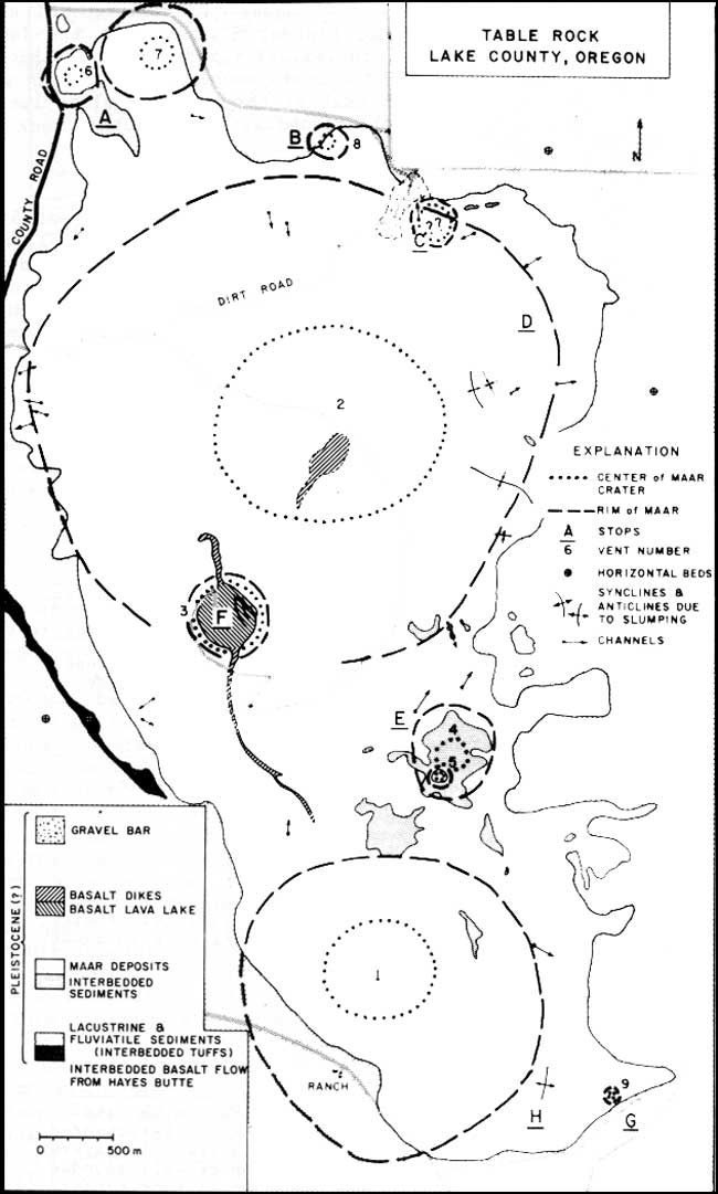
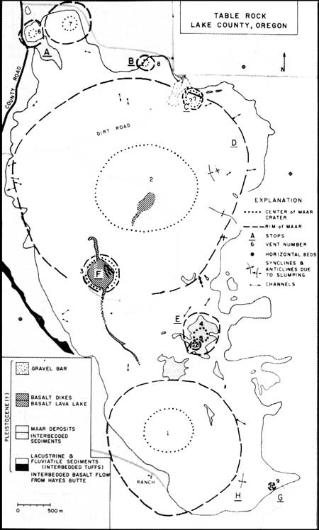
Table Rock Maar Complex
General Description
Table Rock is a tuff cone located 14.5 km east of the
village of Silver Lake, on the shore of Silver Lake, one of the few
remnants of a much larger Pleistocene lake that once filled the Fort
Rock-Christmas Lake Valley Basin (Fig. 2). The Table Rock tuff cone is
part of a maar complex consisting of the cone, two large tuff rings and
six smaller tuff rings or eroded vents.
This complex forms an elongate, NNW-trending oval 5.6
by 8.8 km. The highest point, about 395 m above the basin floor, is the
crest of Table Rock.
Silver Lake graben, located immediately south of the
tuff-ring complex, is the keystone of a broad 25-km-wide structural
arch that forms the southwest boundary of the lake basin. The normal
fault defining the east wall of the graben (through which Highway 31
continues over Picture Rock Pass) is parallel to the long axis of the
maar complex and possibly lies beneath it. The fault, however, does not
cut any of the tuff deposits.
The tuff ring complex overlies a 220 m thick section
of lake sediments and interbedded tuffs, and sands and gravels derived
from the Connley Hills. These predominantly lacustrine sediments overlie
the Picture Rock Basalt (Hampton, 1964), a feldspathic diktytaxitic
basalt unit of Pliocene age. The basalt is well-exposed along the
southern edge of the lake basin, especially along Highway 31, south of
the Table Rock Complex. The Picture Rock basalt, consisting of
individual flows up to 9 m thick, with an aggregate thickness of over
230 m, dips into the basin where it is the main aquifer tapped for
irrigation (Hampton, 1964). South and east of the basin, shallow
lacustrine and flood plain deposits and maar deposits are interbedded
with the Picture Rock basalt (Walker et al., 1967).
Stop A, Table Rock Complex
Park on the county road, walk east along the gully south of vent 6
(bluff on north) for about 350 m. Sediments underlying the Table Rock
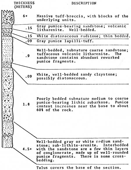
Complex are well-exposed here (Fig. 8). In contrast with well-bedded
diatomites found on the east side of the complex, these consist of
interbedded volcanic litharenites, lithic arkoses, diatomaceous siltstones
and lapilli-tuff that form an outwash apron around the Connley
Hills. The Connley Hills, located northwest of Table Rock consist of a
basaltic shield and intermediate to silicic domes and flows. They were
an island, 6.4 km wide and 19 km long, throughout the late history of
the lake basin. The sediments are higher than those of the basin and
may have been deposited in a small depression between the large
tuff ring (2) and the hills to the north.
|
|
Figure 8a: Table Rock tuff ring complex. (click on image for an enlargement in a new window)
|
|
|
Figure 8b: Section of sediments exposed under the norhtwest corner of
the Table Rock tuff ring complex.
|
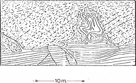
The sediments are deformed beneath thick units of
hyaloclastic tuff-breccia and penetrate the tuffs as mudstone dikes;
the dikes vary from <2 cm to 3 m thick. They have sharp, irregular
boundaries and bulbous, ovoid and sheet-like shapes (Fig. 9). The
entire sedimentary section is deformed here. Away from the contact with
the tuff breccia these units are flat, but here they dip beneath the
tuff ring at angles of 30 to 40 degrees. Similar features are visible in
finely-laminated diatomite beds under the 7-mile Ridge Complex (see map,
Fig. 2). It isn't known if the tilting is due to subsidence around the
crater or to loading by the massive tuff-breccia.
|
|
Figure 9: Diagram of deformation pattern at the
tuff-breccia (stippled) - sediment (plain) contact, below tuff ring #2,
Table Rock tuff ring complex. Uppermost layers of sandstone and mudstone
are intruded into the basalt tuff-breccia as dikes. Deformed bedding
planes are preserved within the dikes, although nearly pinched off where
the dike enters the breccia. Bedding below the contact is also deformed
by small scale faults.
|
The plastically deformed sediments, many of which
retain original bedding features within dikes, suggest that the
sediments were water-saturated when buried by the overlying massive
hyaloclastic breccias.
The unstable foundation upon which the tuff-ring
complex rests may also account for some large-scale deformation of
hyaloclastic deposits on its eastern flank. Broad anticlines and
synclines within the tuff ring deposits may, in some instances, be
caused by slumping. This is especially true for vent 2, a broad ring
with deposits up to 120 m thick.
The bluff immediately north of Stop A is part of vent
6, a small tuff ring about 240 m in diameter with deposits 25-30 m
thick. The outer slopes of the ring have been eroded, leaving cliffs on
all sides except the SW edge, where its deposits lap onto tuff ring 2.
Typically, the deposits consist of well-bedded, yellow-brown
sideromelane lapilli-tuff in 1-60 cm thick beds. About five percent of
the deposit consists of angular basalt blocks.
Stop B, Table Rock Complex
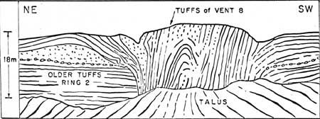
A small vent and tuff ring (vent 8) exposed in
cross-section along the cliff cuts hyaloclastic tuff and tuff-breccia of
the tuff ring 2. The vent is about 33 m in diameter; the tuff ring
remnant has a radius of 120 m. The vent has vertical walls and is filled
with near-vertical, concentric beds of yellow-brown sideromelane
lapilli-tuff, 3 cm to 2 m thick. Near the center of the vent some of the
beds have slumped (Fig. 10). Some beds can be traced from within the
vent into the ring located on the surface of tuff ring 2.
|
|
Figure 10: Sketch of the cliff face in which vent 8,
Table Rock tuff ring complex is exposed. Heavy dots outline
the ground surface prior to the eruption of vent 8. A remnant of a
small tuff ring around the vent is visible.
|
Vertical beds are interpreted as follows: during the
waning phases of activity, vertical vent walls were plastered with bed
after bed of cohesive ash until the vent was filled. Unlike several
other small vents similar to this one, there is no central core of
massive tuff-breccia.
Between Stops B and C there are wave-cut cliffs; at
Stop C, the wave-cut feature breaches the north end of tuff ring 2. The
120 m wide breach through which the road passes, contains a gravel bar
consisting of well-rounded cobbles and pebbles of palagonite tuff and
tuff-breccia eroded from tuff ring 2.
Stop C, Table Rock Complex
Visible here is a steep-walled, U-shaped channel
filled with well-bedded tuff. The channel trends and plunges north away
from the approximate center of vent 2. This is one of 23 U-shaped
channels cut into the rim deposits of vent 2. They range from 1 to 21 m
deep and 2 to 30 m wide. Several channels are traceable for about 150 m,
but original lengths are not known.
The steep sides and U-shape of the channels are
similar to those in deposits of maar volcanoes near Rome, Italy (Losacco
and Parea, 1969; Mattson and Alvarez, 1973) and Koko Craters, Hawaii
(Fisher, 1977). Channels are interpreted to have been cut by base
surges. Infilling beds, which thin and curve up against channel sides
with some extending over the sides onto the rim beds of the tuff cone,
were deposited by base-surge flows and by air-fall. The absence of
consolidated palagonite tuff cobbles within the channels indicates that
they were cut prior to palagonitization and induration of the
tephra.
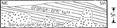
East of the channel, along the inside rim of vent 2,
the effects of palagonitization on hyaloclastic tuffs are well shown.
Well-bedded sideromelane tuffs have been hydrothermally altered to
massive, featureless orange-brown to dark brown, brittle palagonite
tuff. The contact between slightly palagonitized bedded rocks and
hydrothermally palagonitized tuffs is sharp; it is irregular and crosses
bedding planes (Fig. 11). Only the most distinctly graded beds, with
coarse lapilli at the base are preserved in the hydrothermally altered
zones. Beds above the contact are slightly altered sideromelane tuffs;
individual sideromelane pyroclasts consist of a core of brown glass,
rimmed with orange or yellow-orange palagonite. Some pyroclasts,
especially smaller ones, are completely altered, but their relict forms
are preserved. There are also traces of zeolite and calcite cement
between pyroclasts.
|
|
Figure 11: Bedding within the Table Rock maar complex
is often destroyed by palagonitization of the well-bedded tuffs by
late-stage hydrothermal activity. The dotted line traces the contact
between partly palagonitized and completely palagonitized tuff.
|
Below the hydrothermal contact, sideromelane
pyroclasts are completely altered to palagonite, and the rock is crossed
by dessication(?) cracks that break it down into 10 to 40 µm particles.
With the "homogenization" of the rock, grain size differences
responsible for visibility of bedding and sedimentary structures are
destroyed. The end product is a massive, brittle rock composed of clays,
zeolites, iron oxide and calcite cut by NW-trending to W-trending joints
(vertical).
Massive, altered areas within craters suggests that
the alteration is due to reaction of sideromelane pyroclasts (basaltic
glass) with steam seeping through ejecta. This process is being observed
at Surtsey, Iceland (Jakobsson, 1978).
Stop D, Table Rock Complex
Continuing east and then south to the rim of vent 2,
then back down to the central crater area, many physical characteristics
of maar volcanoes may be seen, including planar graded and reversely
graded lapilli-tuffs, cross-bedding (with current directions
uphill, out of crater), bedding plane sags (block sags), and
convolute beds.
Stop E, Table Rock Complex
Park vehicles near the base of Table Rock and walk
southeast about 500 m to the edge of a depression about 45 m deep and
360 m in diameter and open to the lake basin on the east side. The area,
designated as vent 4, formed a crater in tuffs of vents 1 and 2, with
crater walls sloping inward at angles of 30 to 85 degrees. Parallel to
and covering the crater walls are well-bedded, steeply dipping layers of
lapilli-tuff, with an aggregate thickness of 60 m (Fig. 12a).
Yellow-brown lapilli-tuff and tuff-breccia are present in beds ranging
in thickness from 1 mm to 1 m. These beds dip steeply within the vent
and may be traced out of the vent onto the remnants of a small
maar deposit over lying tuffs of vents 1 and 2 (Fig. 12b). Wet, sticky
hyaloclastite tephra were plastered onto crater walls during the waning
phases of the eruptive activity; many have remained in place, but some
sections have slumped and overturned.
|
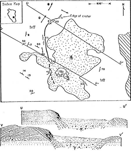
Figure 12a (top): Sketch map of vent areas 4 and 5, Table
Rock tuff ring Complex. The map is represented on the index map (inset)
as a black square. An outline of the Table Rock tuff ring complex is
shown in the index map. The present crater edge of vent 4 is shown with
a double line. Plain areas are bedded tuffs, stippled areas are crater
lake sediments and alluvium, diagonal lines represent lake sediments of
the Fort Rock - Christmas Lake Valley Basin. Vent 5 is located at the
south edge of the crater of vent 4.
Figure 12b (bottom): Cross-sections U-U' and V-V'. The
alternating stipple-line pattern represents bedded tuffs of tuff ring
2, the continuous line pattern represents bedded tuffs of vent 4,
alternating line-dash patterns are crater lake sediments, and dotted
patterns represent lake sediments underlying the tuff ring complex.
(click on image for an enlargement in a new window)
|
Lake sediments consisting of white diatomaceous
mudstones occur within the crater of vent 4. These deposits lie nearly
30 m above the lake basin floor and were deposited in a crater lake
apart from the larger basin.
Within the southern part of the crater of vent 4 is a
prominent oval column of tuff (18 m high, 90 m long) that may have been
the conduit for a small vent (5) (Fig. 13a). The column consists of
concentric, steeply dipping tuff beds that cut across and therefore are
younger than the crater lake sediments of vent 4. Within 2 cm of the
tuff-lake sediment contact, the flat-lying lake sediments are brittle,
(affected thermally by the hyaloclastic tephra of the conduit?) Beds of
sideromelane tuff and lapilli-tuff dip inward from the outer edges of
the conduit of vent 5 at angles of 30 to 80 degrees (Fig. 13). The
center of the conduit consists of massive tuff breccia containing blocks
of lake sediment. As at vent 8 (Stop B) and vent 4, concentric beds with
steep dips suggests that cohesive tephra was plastered onto crater
walls during (waning phases?) of explosive activity. The vents may have
been progressively clogged with tephra somewhat analogous to
clogging of pipes with grout.
|
|
Figure 13a (top): Sketch map of vent area 5, Table Rock tuff ring complex.
Scalloped lines represent the most pronounced unconformities, with the
scallops on the upper beds. The oval, concentric arrangement of the
bedding is shown by the arrangement of attitudes.
Figure 13b (bottom): Field sketch of the southeastern end of
vent area 5.
|
Stop F, Table Rock Complex
Proceed up the dirt and gravel road to the top of Table Rock. Table Rock
is an erosional remnant of a tuff cone constructed above lake level on
the southern rim of vent 2. At present it is a symmetrical cone about
1530 m in diameter at the base, tapering to a diameter of about 360 m at
a height of 360 m above the surrounding plain. The cone is capped with
flat-lying basalt which once filled the crater, but erosion has modified
the original cone, exposing the once-ponded basalt lava lake (Fig. 14).
Dikes extend north and SSE of the crater lake, parallel to the long axis
of the tuff ring complex.
|
|
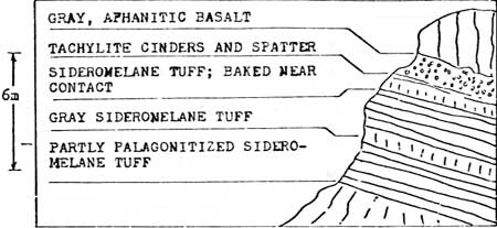
Figure 14: Section of tuff exposed below the lava
lake on the west and south side of the Table Rock tuff cone. A zone of
tuffs (sideromelane) immediately below the former lava lake is not
altered to palagonite. Tuffs elsewhere in the tuff cone are partly
altered to palagonite, implying that dehydration of the tuffs
immediately below the lava lake decreases the instability and resistance
to weathering.
|
On the lower flanks of the cone, the rocks are mostly hyaloclastic
tuffs; yellow-brown or orange sideromelane and palogonite lapilli-tuff
occurs in 1 mm to 2 m thick beds. Near the summit, the uppermost
hyaloclastites are overlain by 1.5 to 6 m of massive black or red
cinders and bombs from fire-fountaining (Strombolian eruption) that
preceded the filling of the crater with lava (Fig. 15).
|
|
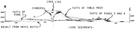
Figure 15: Cross-section, Table Rock.
(click on image for an enlargement in a new window)
|
The lava lake is vertically jointed high-alumina basalt (Table 1).
Blocks of the lava have slumped toward the east, leaving 2-3 m high
scarps along NNW-trending fractures.
Table 1. Chemical analyses of basalts from the Fort Rock - Christmas
Lake Valley Basin. X-ray fluorescence analyses by G. Heiken.
| Sample No. | 1 | 2 |
3 | 4 |
| SiO2 | 50.54 | 50.34 | 50.67 | 52.39 |
| Al2O3 | 16.18 | 15.67 | 17.28 | 16.02 |
| FeO (total) | 10.03 | 10.82 | 10.87 | 8.49 |
| MgO | 6.63 | 8.08 | 7.05 | 6.48 |
| CaO | 9.90 | 10.33 | 10.12 | 9.73 |
| Na2O | 2.70 | 3.09 | 2.42 | 3.33 |
| K2O | 0.59 | 0.39 | 0.39 | 0.86 |
| H2O+ | 0.2 | 0.0 | 0.0 | 0.8 |
| H2O- | 0.2 | 0.3 | 0.6 | 0.6 |
| TiO2 | 1.37 | 1.68 | 1.37 | 1.23 |
| MnO | 0.19 | 0.19 | 0.19 | 0.16 |
| Total | 98.53 | 100.9 | 100.95 | 100.09 |
1. Basalt flow in the lava lake of tuff cone 3, Table Rock tuff ring complex.
2. Lava Lake in the crater of the north tuff ring, Table Mountain.
3. Basalt from a dike which crosses the largest tuff ring in the Seven-Mile Ridge tuff ring complex.
4. Pahoehoe flow from Lava Mountain.
|
Why is the shape of Table Rock tuff cone different from the broad, low
maars of most of the complex? A possible answer is the depth of
explosive steam generation where ascending magma interacted with water.
The broad, low tuff rings may have resulted from shallow phreatomagmatic
explosions where magma nearly reached lake level. Shallow steam
explosions would likely produce broad explosion craters, low fragment
trajectories and base surges resulting in broad, low rim deposits of the
tuff rings. The base of the Table Rock tuff cone is, however, located on
the rim of vent 2 above former lake level. About 210 m below the cone
base is a highly permeable aquifer within basalt flows which lies
beneath essentially impermeable diatomite beds. In contrast with shallow
explosions, phreatomagmatic explosions within the aquifer may
have been guided by the conduit, resulting in higher angle trajectories
and a higher, steep-sided cone.
There is an excellent view of the entire complex and
the Fort Rock-Christmas Lake Valley basin from the top of Table
Rock:
South - The edge of the basin, consisting of
normally faulted Picture Rock Basalt of Pliocene age (Hampton, 1964).
Silver Lake is located within a graben that is the keystone of a broad
arch. The Table Rock Complex is situated along one of these normal
faults, but not cut by it.
Also visible are wave-cut terraces and beach deposits
that border the basin at an elevation of 1336 m. The lake basin is about
64 km long and 40 km wide, with numerous islands such as Hayes Butte and
the Connley Hills, NW of Table Rock. The lake probably existed from
mid(?) Pliocene to late Pleistocene time. During that period, eruptions
of basaltic magma along normal faults that cut across the basin produced
maars within and immediately adjacent to the lake and cinder cones and
flows beyond the lake margins.
East - 13 km east of Table Rock and
overlapping the basin margin is Seven-Mile Ridge, a NW-trending group of
five overlapping maars. The complex is 12 km long and 3.2 to 4.8 km
wide. The best preserved maars are at the basin edge above the former
lake level; they drape over a 61 m high fault scarp. The two
northernmost maars have been eroded by wave action to flat-topped mesas,
9 to 18 m high.
Stop G. table Rock Complex
This stop, at the southern end of the table Rock
Complex, is best reached by dirt roads from near the junction of State
Highway 31 and the southern route to the village of Christmas Valley.
Vent area 9, a small, tuff-filled conduit similar in size to vent 5,
crops out as a 6 to 9 m high knoll at the edge of a wave-cut terrace. It
is about 30 m in diameter. Tuff beds, 1 cm to 75 cm thick, are
concentric and are plastered onto vent walls (wails now unexposed). The
core of the vent is massive, palagonitized tuff (Fig. 16).

|
Figure 16a (top): Sketch of vent 9, Table Rock tuff ring
complex, showing the concentric arrangement of tuff beds around the
outer edges and massive tuff in the center. Stop G.
Figure 16b (bottom): Sketch map of vent 9. Dotted lines represent the geoemetry
of beds which are actually less than a centimeter to several meters
thick. The scale on the right is 30 meters long.
|
Stop H, Table Rock Complex
About 450 m west of stop G. on the southeastern flank
of vent 1, only two ridges remain as erosional remnants of vent l. These
ridges rise about 95 m above the lake basin floor. Originally this maar
may have been nearly 3 km in diameter.
The ring is composed of palagonitized sideromelane
tuff, lapilli-tuff and tuff-breccia. The rocks form
brownish-gray deposits on the outer flanks and ridge tops and
orange-brown deposited within the crater. On the flanks, the tuff beds
are in uniform, 1 to 2 m thick layers. Within the crater, however,
hydrothermal activity has completely palagonitized and "homogenized"
the tuff as is the case in vent 2.
Deposits in some parts of ring 1 are deformed by
slumping and are characterized by convolute bedding. The 61 m thick
section of tuffs at Stop H are folded into a steep, overturned anticline
in sharp contact with underlying, undeformed beds (Fig. 17). The glide
plane for this slump is within the tuff sequence that dips outward (SE)
from the vent at an angle of 6 degrees.
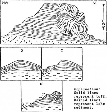
|
Figure 17a (top): Slump structure in bedded tuff on the east edge of Tuff Ring
1, Table Rock. Stop H.
Figure 17b (bottom): Diagrams illustrating the history of events leading
to the formation of the slump illustrated in Fig. 16b.
Explanation: Solid lines represent tuff. Dashed lines represent
lake sediment.
b. Formation of anticline-like structure typical of tuff rings by
deposition of tuffs during eruption(s).
c. Masses of bedded tuff slump into the crater.
d. Unstable tuff remaining on the outer flank of the ring slides toward
the southeast along a core competent detachment horizon.
|
|
|
END OF FIELD TRIP
Return to Bend, via Oregon Highway 31. For more
information on the region, see the enclosed references.
|
REFERENCES
Fisher, R. V., 1977, Erosion by volcanic
base-surge density currents: U-shaped channels. Geol. Soc.
Amer. Bull. 88, 1287-1297.
Hampton, E. R., 1964, Geologic factors that control the occurrence and
availability of ground water in the Fort Rock basin, Lake County,
Oregon. U.S. Geol. Surv. Prof. Paper 383B, B1-B29.
Heiken, G. H., 1971, Tuff rings: examples from the Fort Rock
- Christmas Lake Valley basin, south-central Oregon.
Jour. Geophys. Res., 76, 5615-5626.
Jakobsson, S. P., 1978, Environmental factors controlling the
palagonitization of the Surtsey tephra, Iceland. Bull. Geol. Soc.
Denmark, 27, 91-105.
Lorenz, V., 1970, Some aspects of the eruption mechanism of the Big Hole
maar, central Oregon. Geol. Soc. Amer. Bull. 81B,
1823-1830.
Lorenz, V., 1971, An investigation of volcanic depressions. Part IV.
Origin of Hole-in-the-ground, a maar in central Oregon.
NASA Progress Report, NGR-38-003-012, 113 p.
Lusacco, U. and Parea, G. C., 1969, Saggio di un atlante di strutture
sedimentarie e post-sedimentarie osservate nelle piroclastiti del
Lazio. Atti Soc. Nat. e Matem. di Modena, 94, 30 p.
MacLeod, N. S., Walker, G. W., and McKee, E. H., 1976, Geothermal
significance of eastward increase in age of upper Cenozoic rhyolite
domes in southeastern Oregon. in Proc., Second United Nations
Symposium on the Development and Use of Geothermal Resources,
465-474.
Mattson, P. A. and Alvarez, W., 1973, Base surge deposits in Pleistocene
volcanic ash near Rome. Bull. Volcanol., 37, 553-572.
Peterson, N. V. and Groh, E. A., 1961,
Hole-in-the-ground, central Oregon. Meteorite Crater or
volcanic explosion? The Ore Bin, 25, 73-88.
Peterson, M. V. and Groh, E. A., 1963, Maars of
south-central Oregon. The Ore Bin, 25,
73-89.
circ/838/roadlog6.htm
Last Updated: 28-Mar-2006
|