|
LAKE MEAD Construction of Boulder Dam |
|
FEATURES OF CONSTRUCTION
Principal features of construction are the four diversion tunnels, two on each side of the canyon, to detour the river around the damsite during construction; the cofferdams, one above the damsite, the other below, to turn the river into the diversion tunnels and keep the damsite dry; the dam which will raise the river water surface a maximum of 584 feet; the two spillways, one on each side of the canyon, to carry the reservoir overflow; the four intake towers to take water from the reservoir for the turbines of the power plant, for downstream requirements and for reservoir regulation; the penstock and outlet system to carry water from the intake towers to the power plant or to outlet works; and the U-shaped power plant which nestles close to the walls of the canyon immediately downstream from the dam.
|
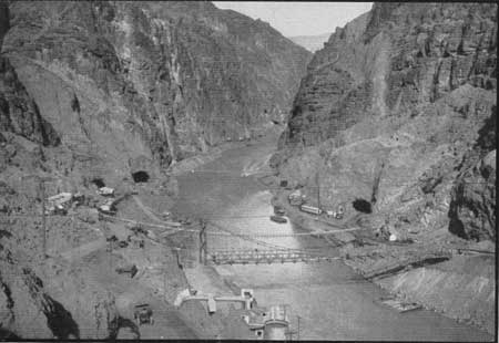
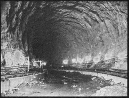
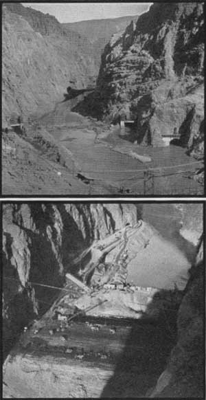
| View Upstream February, 1932, Showing Tunnel Outlets |
PROGRAM OF CONSTRUCTION
The general program of construction, all features of which were overlapping, was to drive and line the four diversion tunnels, build the cofferdams, excavate the dam abutments and river channel, build the dam, construct the spillways, intake towers, penstock and outlet system, outlet works and power house. Finally the outlet works and their related pipes will be installed in the downstream plugs of the inner diversion tunnels. As soon as the dam, intake towers and canyon wall outlet works were nearing completion and the solid concrete plugs had been poured in the upstream sections of the inner diversion tunnels, the steel bulkhead gate was lowered (on February 1, 1931) at the inlet of the Arizona diversion tunnel farther from the river, and water started rising back of the partly completed dam, under control of slide gates installed in the plug in the Nevada Outer diversion tunnel. A little more than a year later the slide gates in the plug were closed and the flow downstream from the dam then was regulated by the gates at the bases of intake towers, 260 feet above the old river bed, and the needle valves in the canyon wall outlet works.
|
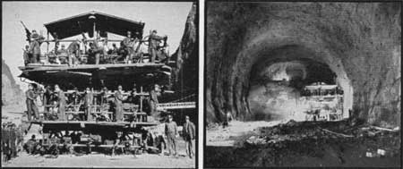
| Drilling Jumbo (left); Drilling Jumbo at Tunnel Face (right) |
EXCAVATIONS FOR DIVERSION TUNNELS
The contract for construction of the dam, power plant and appurtenant works was awarded Six Companies, Inc., on March 11, 1931, and by May 16, 1931, the contractor had erected a temporary camp, built pioneer roads to the damsite and started excavations for the diversion tunnels. The first operation for this latter work was to drive 12-foot by 12-foot pilot tunnels as top headings, starting from all portals and from intermediate points reached through adits driven in canyon walls, thus securing sixteen faces where excavations could proceed. Headings were then enlarged to 41-foot by 16-foot sections, starting at all portals and finally the remaining 15 feet in the invert was removed and the tunnel trimmed to the full 56-foot diameter.
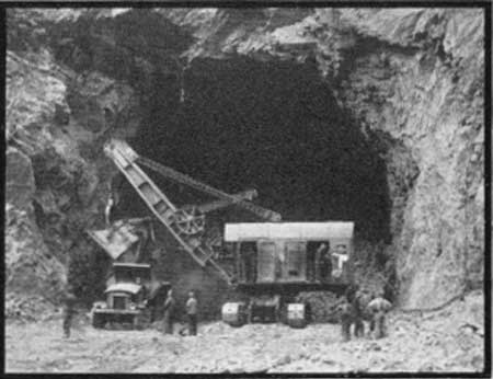
Specially built equipment, termed "Jumbos," were originated by the contractor for this work. The one for drilling the 41-foot by 56-foot headings mounted 30 compressed air drifter drills, was transported by a 10-ton truck, and by means of this equipment, 110 holes 20 feet deep could be drilled and loaded in 4 hours. Each blasting round broke an average tunnel length of 17 feet, loosening 1,000 tons of rock which was mucked in 4 hours by a 3-1/2-cubic yard electric shovel and a fleet of 8- and 10-cubic yard trucks.
All 41-foot by 16-foot headings were holed through on April 6, 1932, and the four tunnels were excavated to full section by May 27, 1932. Rock removed amounted to 1,500,000 cubic yards, requiring 3,161,000 pounds of dynamite, or 2,38 pounds of powder per cubic yard.
|
| Tunnel Excavation |
|
| Completed Excavation |
|
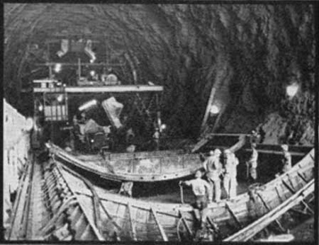
| Lining Invert and Sidewall |
|
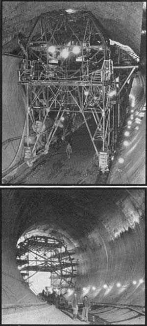
| Arch Lining . . . Gun Carriage in Foreground (top); Completed Tunnel (bottom) |
LINING DIVERSION TUNNELS
Lining the tunnels with a 3-foot average thickness of concrete was accomplished by forming and pouring the invert section in the ordinary manner, similar to that used for concrete highways and sidewalks; then pouring the side walls behind huge steel forms, weighing 250 tons per 80-foot section; and finally building the arch by forcing concrete above massive steel forms by compressed air at 100 pounds pressure per square inch.
The low level mixing plant produced all concrete for tunnel lining, and transportation from the plant was first by truck and then by gantry crane. Buckets used were of the 2-cubic yard spout type or 4-cubic yard agitators. Curing of finished concrete was secured by spraying with water or painting the surface with an asphalt mixture (Hunt process). After lining, holes were drilled through the concrete into the rock and a cement and water grout was forced into all rock crevices and openings around the tunnel. Approximately 300,000 cubic yards of concrete were placed in the diversion tunnel linings in a period of 368 days.
|
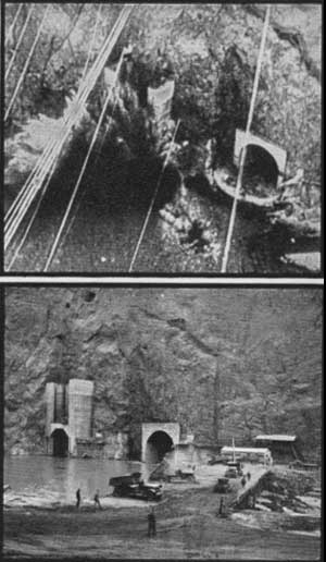
| Initial Blast for Diversion (top); Building Temporary Dam for Diversion (bottom) |
|
| Temporary Dams In Place (top); Building Upper Cofferdam (bottom) |
DIVERSION
By November 13, 1932, eighteen months after the first excavation, the Arizona tunnels were ready to carry the river flow, and simultaneous blasts on that date at inlets and outlets signalized the first diversion. Preceding that event, a pile trestle bridge had been thrown across the river a short distance downstream from tunnel inlets and soon after a part of the river started pouring through the Arizona tunnels, trucks commenced dumping muck from the bridge to form a temporary barrier and force the entire flow out of the old river bed. Within twenty four hours the bridge was covered by a dam which was raised and widened until practically all seepage was eliminated. Another temporary dam of earth and tunnel muck was meanwhile pushed out from the Arizona to the Nevada side at a location upstream from the tunnel outlets. The water entrapped between the two temporary barriers was then pumped out and excavations were started across the entire channel for the upper and lower cofferdams.
|
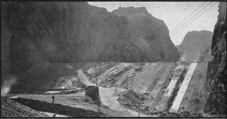
| Completed Upper Cofferdam . . . View Downstream |
COFFERDAMS
The centerline of the crest on the upper cofferdam was 800 feet upstream from the axis of Boulder Dam and 650 feet downstream from the nearest tunnel inlet. The crest of the lower structure was 3,320 feet downstream from the main dam and 700 feet upstream from the nearest tunnel.
The essential characteristics of both cofferdams were thick fills of rolled earth, the long slopes of which were protected by a concrete slab or rock fills. Concrete percolation stops extended from base to crest at each canyon wall to impede the possible flow of water along the walls. The upstream slope of the upper cofferdam was faced with a 6-inch reinforced concrete slab, of 4 acres in extent, and a sheet steel piling cutoff was driven to bedrock across the upstream toe. Concrete curbs and rubber seals connected the face paving with the canyon walls and steel piling. The downstream slope of the lower cofferdam was protected from eddy flow of the river by a massive barrier of 90,000 cubic yards of rock built immediately downstream. The slopes of both cofferdams toward the main dam were covered with heavy rock fills.
Excavations for the upper cofferdam were carried down to a consolidated gravel foundation 18 feet below the river bed and the removed material transported by truck and train to dump grounds 3 miles up the river. Sand, gravel and clay from deposits in Hemenway Wash, four miles upstream, were hauled by train and truck to the cofferdam, spread by bulldozers on caterpillar tractors, dampened by hose, and rolled by 6-ton sheep's foot rollers. As many as 40 trucks, 4 trains and 5 power shovels worked day and night for two months to complete the fill, moving 510,000 cubic yards of earth, including one 24-hour run of 18,000 cubic yards.
Rock secured from nearby excavations was placed in riprap formation on the upper slope and dumped on the downstream slope. The last work for the structure was the placing of the face paving and rubber seals and completion of the rock fill on the downstream slope. Construction of the lower cofferdam was conducted in much the same manner as for the upper structure, taking into consideration the differences in design previously mentioned.
Dimensions of the upper cofferdam were 750 feet thick at the base, 480 feet wide, 98 feet high, and 70 feet thick at the crest. The lower cofferdam was 500 feet thick at the base, 66 feet high, and 50 feet thick at the crest. The rock barrier had a base thickness of 210 feet and a height of 54 feet. The cost to the Government for the diversion tunnels and cofferdam was nearly twenty-three million dollars.
After diversion of the river was controlled by the slide gates in the plug of the Nevada outer diversion tunnel, the lower cofferdam and rock barrier were removed, the excavated material being hauled out of the river channel. The upper cofferdam will remain in place.
|
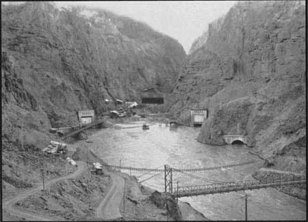
| View of Outlets. Tunnels Carry 79,000 Cubic Feet a Second |
| <<< Previous | <<< Contents>>> | Next >>> |
boulder_dam1/sec3.htm
Last Updated: 01-Feb-2008