|
LAKE MEAD Construction of Boulder Dam |
|
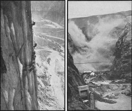
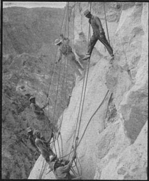
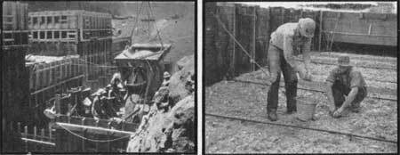
HIGH SCALING
Stripping loose and projecting rocks from the walls of the canyon to protect workers and prevent damage to canyon structures was one of the most hazardous and the most spectacular of all work on the project. Men were lowered by cableways or climbed to their work "over the ropes" where, suspended by safety belts or in bosum chairs, they drilled for blasting and pried off all loose rock.
Stripping was carried on from canyon rim to canyon floor above all structures and the scaling methods were used for excavations of the tunnel portals, dam abutments, intake towers, canyon wall outlet works and power house. "High Scalers" employed for the work, in April, 1933, numbered approximately 400.
|
| Scaling Above Power House (left); Blast on Canyon Walls (right) |
|
| Scaling |
|
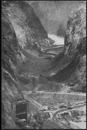
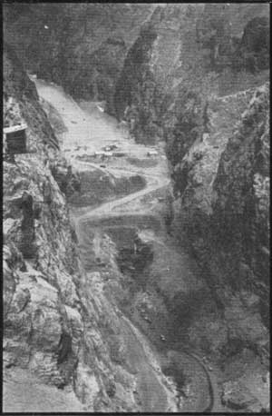
| Debris in Canyon, Following Excavation on Canyon Walls |
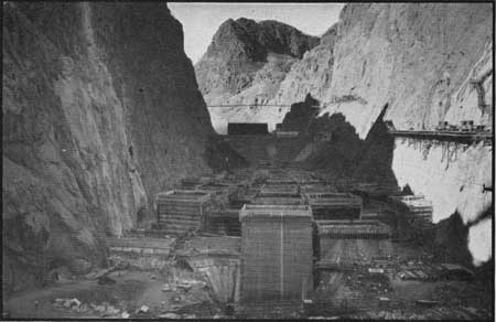
DAM EXCAVATION
Excavations for the dam abutments were started after the river was diverted and completed shortly before cofferdams were built. The cuts are on radial lines of the dam axis at the top, where the water thrust against the dam will be carried primarily by arch action, and are warped to the normal canyon wall in a drop of about 400 feet, the dam section at the base being designed to withstand the water thrust by the weight of the structure.
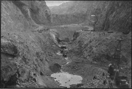
Safely entrenched between the cofferdams, the excavations in the river channel proceeded at a rapid rate. Power shovels, draglines and trucks labored the full twenty-four hours, digging from river bed at elevation 640 down to bedrock on each side of the canyon at elevation 600 and on downward in the 80-foot wide middle gorge nearly a hundred feet more to the low point at elevation 505.6. The sand, gravel and rock removed amounted to more than a half million cubic yards and were hauled by truck to train and transported three miles upstream to a dump ground. During this work, the contractor's average bills per month were $11,000.00 for tires and $45,000.00 for gasoline.
|
| Excavation for Dam Foundation |
|
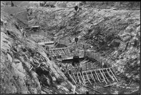
| Dam Excavation Practically Completed |
DAM CONCRETE
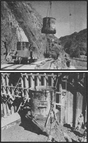
The exposed bedrock was cleaned, forms were built, and on June 6, 1933, the first 16-ton (8 cubic yard) bucket of concrete for the dam was mixed at the low level plant, transported by train beneath cableway No. 6, picked up, swung part way across the canyon, lowered to position and dumped at the signal man's order. Other trains and cableways were brought into action, a 20-ton derrick with 138-foot boom was later added for transference at the upstream face, and by August 31 the middle gorge was filled; seven months after starting, a million yards had been placed; a year later, three million yards had been poured; and all blocks were at crest elevation on March 23, 1935. The average placement in 24 hours was approximately 5,300 cubic yards and over 8,000 cubic yards have been poured in that time.
|
| Pouring First Bucket of Dam Concrete |
|
| 16 Tons Concrete in Transit to Dam (top); Dumping 16 Tons of Concrete (bottom) |
|
| Pouring with Agitator in Constricted Area (left); Final Clean-Up of Dam Pour (right) |
Completion of major features of the dam had taken place before the summer of 1931, thus in less than two years, 1200 men and modern machinery had placed 3,250,000 cubic yards of concrete, a greater volume than that of the Great Pyramid of Egypt, which, according to Herodotus, required the services of 100,000 men for 20 years in its construction.
The dam is of the arch gravity type, the radius of the axis being 100 feet and weight approximately 6,500,000 tons. As completed it is 727 feet high to walkway on crest, 650 feet thick at the base, 1,180 feet long and 45 feet thick at the crest and will raise the water surface 184 feet. For comparison, its height is 1-1/2 times that of the Los Angeles City Hall and only 65 feet less than that of the Woolworth Building in New York City. The base thickness is greater than two normal city blocks and its crest is four blocks long. The dams of its nearest height are the Owyhee, near Ontario, Oregon, which rises 405 feet above bedrock and the Chambon Dam of 446 feet height now under construction in France.
|
| View Downstream September, 1933 . . . Note Cooling Plant and Tower in Lower Cofferdam |
COOLING AND GROUTING THE DAM
The magnitude of the structure is outstanding and the unusual plan of construction presented features of similar note. The vast bulk of the dam has provided a problem in temperature stresses that required much thought and research before a solution was attained. The temperature of the concrete, using standard Portland cement, was raised approximately 40° by the chemical action of setting, and if the dam was allowed to cool naturally, a period of as much as 150 years would elapse before the temperature of the mass reached that of the surrounding medium. During all that time, temperature stresses would be set up, and cracking would result from differential cooling.
To obviate this condition, the dam was built in a group of vertical columns 25 feet to 60 feet in plan, one inch diameter cooling pipes were placed at 5-foot intervals vertically and 5 feet 9 inches horizontally throughout the structure, and grout pipes were in stalled leading to the sides of all columns.
Water from an atmospheric tower at slightly below air temperature was first passed through the 1-inch lines until maximum cooling was secured by this means, then water from a refrigerating plant at a temperature of 35° to 40° F. was turned into the lines, cooling the concrete as low as 42° F. The 14-inch supply lines for the cooling loops were located in the 8-foot slot that passes through the center of the dam. The slot was filled with concrete in 50-foot lifts as soon as cooling of the dam has been completed for that lift.
After a section of the dam, for example from elevation 600 to 650 had been cooled to the specified temperature, the slot was poured to the higher elevation, and a water cement mixture of grout was forced through the grout pipes into the cracks opened up between the columns by the contraction due to cooling. The section thus cooled and grouted was then allowed to resume the temperature of the surrounding medium and the resulting expansion, carried from column to column by the joint filling of grout, places all components of the concrete in compression and prevents cracking, which normally ensues from the opposite or tensile force. Another effect of the cooling and grouting was to force the sides of the dam into close contact with the canyon walls.
The atmospheric tower for the cooling system was located on the lower cofferdam, and the refrigerating plant on a canyon wall bench, just upstream from the cofferdam on the Nevada side. The plant was equipped with three complete ammonia refrigerating units and one standby unit, as well as all pumps required for forcing the water from the cooling water tower through the cooling lines and for circulating the refrigerated water. The cooling capacity of the plant was equivalent to producing 1,000 tons of ice in 24 hours. The rate of flow through each cooling loop was four gallons per minute. Three thousand gallons from the tower and an equal amount of the refrigerated water would be circulated through the dam at one time. The length of cooling pipes in the dam is approximately 580 miles, and grout pipes 200 miles.
Electrical resistance thermometers, strain meters and contraction joint meters were installed in the dam, and records maintained by government engineers. These instruments furnished information of construction as well as provided data for future design.
| <<< Previous | <<< Contents>>> | Next >>> |
boulder_dam1/sec4.htm
Last Updated: 01-Feb-2008