|
LAKE MEAD Construction of Boulder Dam |
|
FABRICATION AND INSTALLATION OF PLATE STEEL PIPE
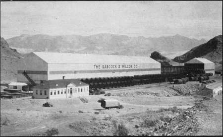
All pipes for the penstock and outlet system are fabricated and installed by The Babcock & Wilcox Company of Barberton, Ohio, under contract with the Bureau of Reclamation. Most of the pipes are too large to be transported on existing railroads and were thus required to be fabricated on the project. The contractor erected a plant for this purpose on the road from Boulder City to the dam, approximately 1-1/2 miles from the top of the Nevada abutment.
|
| Fabrication Plant of The Babcock & Wilcox Company |
Length of the plant with storage yard and connecting government ware house is 970 feet, the width of the building is 90 feet, and height 85 feet. A visitors' gallery has been built across the west end of the plant which is accessible by a stairway on the outside of the building.
Plates of high tensile steel were shipped from the mills of the Illinois Steel Company at Gary, Indiana. In straight runs of pipe the plates for the 8-1/2-foot and 13-foot units were approximately 11 feet long and of sufficient width (26.8 feet to 41.2 feet) to complete a section of pipe. The 25-foot pipe required two plates for a section 11 feet long and the 30-foot pipe, three plates for a 10.5-foot length. Plates for some of the 30-foot pipe weighed 20 tons each, requiring one car for the transportation of only two plates.
The first work of fabrication was marking of the plates to designated patterns and size, shaping them as required and cutting a welding groove along the edges. This latter operation was performed by a specially designed planer 50 feet in length which was equipped with pneumatic clamps for holding the plate in place, and a cutting tool carriage on which the operator rode.
|
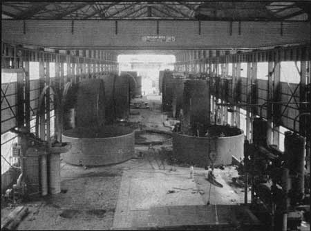
| Interior of Fabrication Plant |
The plate was then conveyed by bridge crane to a 3000-ton hydraulic press where the ends were bent to the prescribed radius, followed by rolling the plate to the required form in a vertical roller 12-1/2 feet in height. The rolled plate was placed on a curved form, tack welded at the ends to other similarly rolled plates (when fabricating 25-foot pipe or over), turn-buckles were placed in position to hold the assembled plates in circular form, the section was turned on its side, placed on rollers and the longitudinal seams were arc welded by automatic welding machines.
After these seams were welded, and necessary stiffner rings were added, by welding, and a fabricated section, (or two or more if a bend was being built) were assembled end to end to form the finished pipe. Huge expansion appliances termed "spiders," were placed within each section to hold their ends coincident, the sections were tack welded together and the girth seams then welded by the automatic machines. Butt straps, into which an adjoining pipe fits when installed in tunnels, were shrunk on and welded to one section of the pipe preceding assembly and girth welding.
|
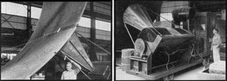
| Taking X-Ray Photograph of Weld (left); 200,000-Volt X-Ray (right) |
The succeeding operation, after welding had been finished, was to subject the longitudinal and girth joints to the scrutiny of a powerful X-ray which provided a photograph of the fusion weld and revealed any defects therein. The X-ray apparatus operated at 100,000 volts and was capable of producing radio-graphs of steel plate up to four inches in thickness. And imperfections were chipped out, refilled with new metal, X-rayed again and the photographs inspected.
The required supporting brackets were then welded to the pipe, the section was picked up by one or more of the 75-ton bridge cranes and conveyed to a stress relieving furnace, placed in the oven, and the temperature raised to 1150° F. The pipe soaked at this heat for a length of time equal to one hour for each inch of thickness of the heaviest plate in the section, and was allowed to gradually cool during a period of several hours. This procedure relieved the stresses set up in the pipe by rolling and welding.
|
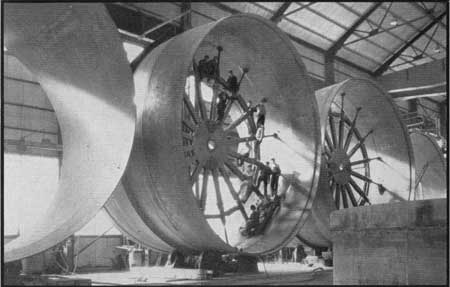
| Sections of 30-foot Diameter Pipe |
|
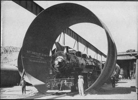
| 100-Ton Locomotive in 30-foot Pipe |
The final act of fabrication was the machining of the pipe ends to exact measurements by means of portable lathes inserted within the smaller sections or by a huge facing lathe, equipped with a 15-foot arm, for the 25-foot and 30-foot diameter pipes. The interior of the pipe was then shot blasted to remove all scale and coated with coal gas tar. The exterior was cleaned by air and wire brush, and painted with a primer coat of red lead.
All pipe of 13 feet diameter or less, were transported by railroad from the plant to a cableway pit on the Nevada rim, lowered by the Government cableway to cars at landing platforms and hauled to position by hoists.
The 25-foot and 30-foot pipes were loaded on an 185-ton trailer, pulled by two 60 H.P. tractors to the Government cableway, lowered onto specially designed railroad carriages at landing platforms, taken sideways into penstock header tunnels or inner diversion tunnels, and pushed endwise into position.
|
| The Highway from Boulder City to Kingman, Arizona, Crosses Black Canyon on the Dam Crest. This Route is a Northern Alternate of U. S. Highway 66 from Kingman to Barstow. California. |
|
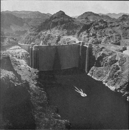
| Mead Lake at the Beginning of the 1936 Flood Season. Its Depth is 270 feet, Length 76 miles, and, Although Only One-Eighth Full, is Already the Largest Artificial Body of Water in the World. Speed Boats and Slower Traveling Craft Transport Visitors from the Boat Landing into Black Canyon, to the Dam Face and Return, a Distance of Ten Miles for the Round Trip. Boats may be Chartered at Reasonable Rates for Excursions up the Lake through the Fiords of Boulder Canyon, Iceberg Canyon and the Lower Reaches of Grand Canyon, a Region of Indescribable Scenic Wonder. |
For installation, the butt strap on one end of a pipe is heated by a gas ring and the end of the connecting pipe pushed within the strap. Both butt strap and included pipe are then fastened together by rivets or pressure pins and the outer end of the butt strap caulked water tight.
Anchors for the pipe are placed from 185 feet to 461 feet apart and the center connection between anchors is not made until the pipe is at a temperature of 50° F. or less. This temperature is approximately the same as that of the pipe when filled with water, thus reducing the temperature stress in the pipe to a minimum.
The weight of pipe fabricated amounted to 88,000,000 pounds, or more than 900 carloads. Approximately 76 miles of electric welding were required, using 1,000 tons of welding rod. Film for the X-ray photographs if placed end to end would extend 29 miles. The largest pipe section was 30 feet in diameter, 22 feet long, had a plate thickness of 2-3/4 inches, and weighed 186 tons, including 5 tons of weld metal, nearly equal to the weight of two of the largest locomotives that operated on the project.
|
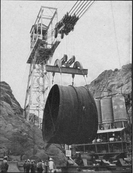
| Transporting a 30-foot steel pipe section from Canyon rim to tunnel portal by the 200-ton capacity cableway. The section forms a part of one of the pipe lines that will carry water from the reservoir to the power plant. |
GOVERNMENT CABLEWAY
The permanent cableway, built for Government use by contract with the Lidgerwood Company of Elizabeth, New Jersey, is employed during the construction period for lowering the steel pipe, power house machinery, structural steel and other supplies, and later to convey replacements and new machinery for the power plant from canyon rim to landings downstream from the power house.
Location of the cableway is 1050 feet downstream from the dam crest and the track cables cross the canyon directly above the portals of all construction adits, where permanent concrete landings have been built. Its nominal rating is 150 tons, but loads of more than 200 tons, including track carriage and fall blocks, are carried by the track cables. These latter are six in number, each 3-1/2 inches in diameter, spaced horizontally at 18-inch centers. Their anchorage in canyon walls is accomplished by driving tunnels 50 feet to 80 feet long, excavating an eighteen-foot bulb at the ends of the tunnels, connecting the cables by plates and eye bars to a 13-foot by 13-foot structural steel grid in the bulb and pouring bulb and tunnel full of concrete. The pull on each canyon wall anchorage with a load of 150 tons at the center of the canyon is calculated to be 2,000,000 pounds.
The span between the Nevada head tower and Arizona anchorage is 1200 feet and the maximum lift approximately 600 feet. The track carriage weighs 19 tons and travels on 48 wheels. Lifting is done by two hoists, each 13 feet in diameter and 17 feet long, operating through an eight part line to the 1-ton fall blocks which are connected to the load. Conveyance across the canyon is accomplished by a third hoist and two endless cables. The hoisting speed is 30 feet per minute with loads of 40 tons or over and 140 feet per minute with lighter loads. Conveying speed is 240 feet per minute. Power is delivered at 2300-volt alternating current and transferred to direct current by a motor generator set. Each hoisting drum is driven by a 175 H.P. D.C. motor and the conveying drum by a 400 H. P. motor. Operation is by remote control from any of the five stations near landing platforms.
|
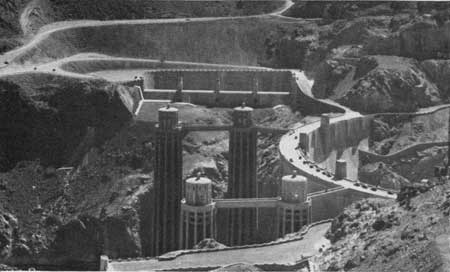
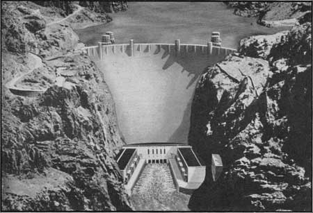
| The Dam and the Power House as They Will Appear Upon Completion |
POWER PLANT
Construction of the powerhouse was started in 1934 and it is expected that the first electricity will be generated in 1936. The building was erected by Six Companies, Inc., but installation of machinery is by Government forces.
The massive U-shaped structure of the power plant is located immediately downstream from the dam, the wings nestling against the canyon walls and the connecting section resting on the downstream face of the dam. The length of each wing is approximately 625 feet and the dam section 300 feet, or a total of more than 1/4 mile.
Lowest concrete in any power house footing is at elevation 550 and the roof is at 780, a difference in height of 230 feet, or nearly 20 stories. The power house will rise 155 feet above low water surface. The roof is 4 feet 6 inches thick, covers nearly four acres (equal to two city blocks) and is composed of seven laminations, two of these being reinforced concrete, another asphalt paving and others of sand and gravel.
Installed capacity of the power plant will be 1,835,000 H.P. consisting of fifteen 115,000 H.P. units and two of 55,000 H.P. Four of the larger units and one of the smaller will be installed during the present period of construction and the others as required to supply the growing demand for power. The turbines will operate under a maximum head of 582 feet, a minimum head of 422 feet, and an average head of 520 feet. The continuous firm power output upon completion of the plant is estimated to be 663,000 horsepower, which will require a continuous flow, at minimum head, of 17,000 cubic feet per second of water. This latter figure is approximately equal to the uninterrupted flow over a yearly period for 12,000,000 acre feet, the minimum active storage in the reservoir.
Materials to be furnished for present construction of the power house and plant comprise 227,000 cubic yards of concrete, 243 cars of reinforcing steel, 20,000 tons of machinery, and 9,000 tons of structural steel including 5 miles of 33-inch I beams and 88 trusses 67 feet to 73 feet in length. Among the items of machinery are vertical shaft, 150 r.p.m. turbines equipped with scroll cases 40 feet in width; generators of 82,500 k.v.a. rating to be operated at 36,500 volts and weighing 905 tons each; transformers to step up the voltage to 305,000 volts, weighing 205 tons each, and butterfly valves measuring 14 feet across the valve chambers.
| <<< Previous | <<< Contents>>> | Next >>> |
boulder_dam1/sec7.htm
Last Updated: 01-Feb-2008