|
LAKE MEAD Construction of Boulder Dam |
|
SPILLWAYS
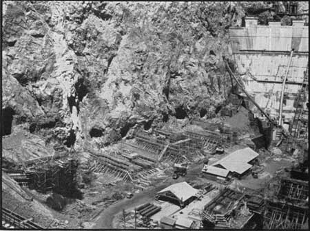
Flow of water from the reservoir will normally be regulated by the amount required for the turbines of the power plant or be by-passed around the plant through the needle valves in the outlet works, to satisfy downstream demands or to lower the surface of the reservoir. Under exceptional conditions when the reservoir is full as a result of unusually large floods, or if it is deemed advisable to lower the surface in advance of a threatened flood, the reservoir overflow will pour over weirs into spillway channels, plunge 500 feet down inclined shafts to outer diversion tunnels and emerge in the river channel below the dam.
Each spillway is capable of passing 200,000 cubic feet per second of water, equal to the maximum recorded flow through Black Canyon. More than 11,000,000 horsepower, in terms of falling water, would be released by a spillway operating at capacity and the velocity of flow as the water passed into the diversion tunnel would be at the rate of 175 feet per second or 120 miles per hour.
The length of a spillway is approximately 650 feet in open section and the concrete lined channel is 150 feet wide at top and 125 feet average depth. The largest battleship could be floated in the structure if the inclined shaft were dammed at the portal. The Arizona shaft is 88 feet high and 98 feet wide at the portal and narrows gradually to a 50-foot diameter. A concrete plug, 400 feet long, has been placed in the diversion tunnel immediately upstream from the intersection with the inclined shaft.
|
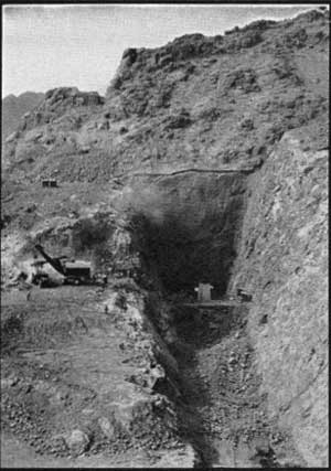
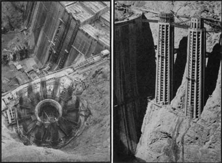
| Excavation for Nevada Spillway Looking Toward Inclined Shaft |
|
| Lining Channel of Nevada Spillway |
|
| Completed Lining—Nevada Spillway |
Four steel drum gates, each 100 feet long and 16 feet high, and weighing a half million pounds, are erected on each spillway crest. The gates ordinarily lie in weir recesses and are hydraulically raised by the rising waters of the reservoir. The elevation of the permanent crest is at 1205.4 feet above mean sea level and top of the gates, when raised, at 1221.4 feet or 10.6 feet below the Boulder Dam crest.
The spillway channels were blasted from solid rock, using the drill jumbos from the tunnels and removing the muck by power shovels and fleet of trucks. The inclined shafts were excavated by first driving a 7-foot by 14-foot top heading from the diversion tunnels upward, enlarging these pioneer bores to 14-foot slots extending to the lower walls of the shafts, and breaking down the remaining side sections into the slot, working in horizontal benches from the top downward. The muck was removed from the diversion tunnels by power shovels and trucks.
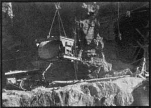
Concrete for lining the channels and inclined shafts was transported by truck and cableway to the spillways in 4-cubic yard agitators. Draglines equipped with 100-foot booms, capable of conveying 1 cubic yard of concrete, were employed to transfer the concrete to pouring site in the channels. The shafts were lined behind wooden forms, receiving concrete via belt conveyors and chutes, from agitators brought down from the shaft portals by rail. Approximately 600,000 cubic yards of rock were removed for spillway excavations, and the materials required for construction include 130,000 cubic yards of concrete and 2,000 tons of drum gates.
|
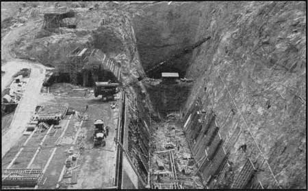
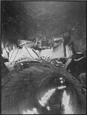
| Intersection Nevada Spillway Shaft and Diversion Tunnel |
|
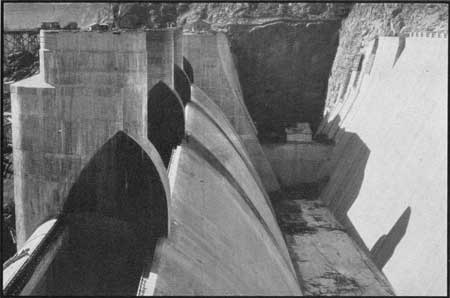
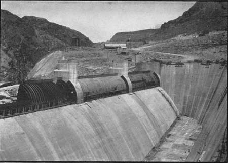
| Arizona Spillway Showing Two Gates Installed |
INTAKE TOWERS
For production of electrical energy and normal reservoir regulation, water from the reservoir will flow through the gates of intake towers into penstock headers and penstocks to the turbines of the power plant, or into penstock headers, outlet headers, and outlet conduits to the needle valves in the outlet works.
The intake towers are four in number, two located on each side of the canyon immediately upstream from the dam to which they are connected by steel and concrete bridges. The platform at the top of each tower, on which the hoist house is located, is at the same elevation as the crest of the dam. The towers are set on benches cut in the canyon walls 210 feet above the river bed to secure a basin for silt storage and thus obtain a clear water flow to the turbines. Excavations were conducted by scaling methods, the muck being dumped into the canyon below, loaded by power shovels and hauled by trucks to dump grounds in side canyons above the high water surface of the river. Each cut is 110 feet in diameter at the base and those on the Nevada side are 300 feet in depth.
|
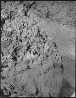
| Scaling far Intake Towers |
|
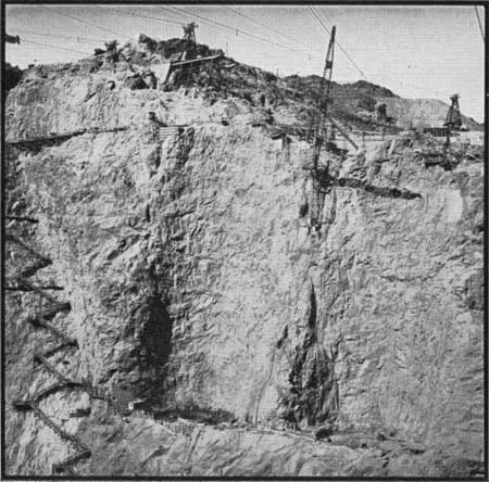
| Completed Excavation for Nevada Intake Towers |
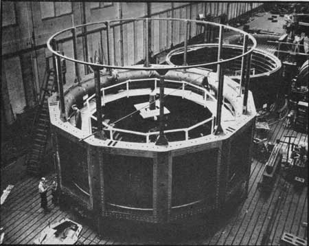
Essentially the towers are hollow cylinders 395 feet high, 82 feet in diameter at the base and are equipped with cylinder gates at the bases and 150 feet higher. From the exterior they resemble fluted columns as 12 recesses, formed by the tower fins, extend from base to top. Trash racks are installed in these recesses to prevent debris from entering the gate openings. Slides are also placed in each fin from top to bottom of the tower, down which emergency gates can be lowered to isolate any gate for repairs. The cylinder gates are 32 feet in diameter and 11 feet high, each weighing approximately a half million pounds. Electric hoists located in the house at the top of each tower raise and lower the gates vertically.
Concrete for the towers was poured at the high level plant into 4-cubic yard buckets and brought by rail, or rail and cableway, to the canyon rims above the towers. Huge derricks of 15-ton capacity and equipped with booms 180 feet in length picked up the buckets and lowered them to central hoppers, above the completed sections of the towers, from which the concrete flowed through radial chutes to all fins, beams and barrels.
Materials required for construction include 200 tons of steel gates, 84,000 cubic yards of concrete, and 6,500 tons of reinforcing steel. An item of note is that approximately 150 pounds of steel are used for each cubic yard of concrete.
|
| Looking Down on Nevada Tower (left); The Nevada Intake Towers (right) |
PENSTOCK AND OUTLET SYSTEM
The penstock and outlet system consists of a series of tunnels and included pipes leading from the bases of the intake towers to the power plant and outlet works. The system is duplicated in most particulars on each side of the canyon, therefore for simplicity only one side will be described.
A penstock header tunnel, excavated to 41-foot diameter and lined with a 2-foot thickness of concrete, drops from the base of the downstream intake tower through a vertical curve of 70 feet radius to center line elevation 820. It then continues horizontally downstream past penstock tunnel openings and a construction adit to an outlet header tunnel of 31 feet diameter excavated section, from which outlet conduits branch to needle valves in the canyon wall outlet works. A 30-foot diameter steel pipe is placed in the tunnel from the base of the tower to a point downstream from the construction adit where it is reduced to a 25-foot pipe and then further reduced gradually to a 20-foot section at the entrance of the last two outlet conduits downstream.
|
| Tower Gate and Entrance Liners at Factory |

|
| Excavating Penstock Header Tunnel (left); Lining Penstock Header Tunnel (right) |
The header pipe rests on piers and supports for most of the tunnel length, but is anchored by filling the spaces between pipe and tunnel lining in the vertical curve below the tower, upstream and downstream from penstock openings, and from the construction adit downstream. The length of the penstock and outlet header tunnel is 1,550 feet on the Nevada side and 1,375 feet on the Arizona side.
The four penstock tunnels that branch from the penstock header tunnel were excavated to 21-foot diameter and lined with 18 inches of concrete. Pipes, 11 feet in diameter, rest on supports poured monolithic with the lining and run from the 30-foot pipe to butterfly valves in the power plant. The pipes are anchored just below their upper ends and immediately above the canyon wall tunnel portals. Lengths of the inclined penstocks are approximately 330 feet in Nevada and 310 feet in Arizona.
|
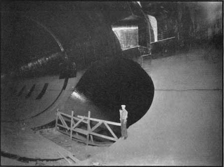
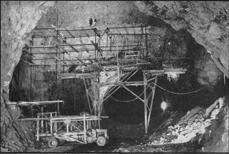
| Intersection of Penstock and Penstock Header Tunnels |
|
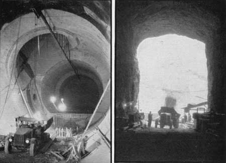
| Intersection . . . Incline from Arizona Tower and Division Tunnel (left); Arizona Construction Adit (right) |
|
| Conveying Concrete to Penstock Tunnel |
The construction adit is 26 feet wide, 43 feet high, 150 feet long and is lined only in the floor section. Its purpose is to provide means of access to the header tunnels for installing the 25-foot and 30-foot pipes.
Outlet tunnels, six in number, are horizontal, 140 to 175 feet in length, have been excavated to a 13-foot horseshoe section and are not lined. Outlet conduits, 8-1/2 feet in diameter are centered in the tunnels and the space between pipe and rock filled with concrete. A slide gate and 84-inch needle valve is installed at the river end of each conduit. The canyon wall outlet works, containing the needle valves, has been erected on a bench cut in the canyon wall 168 feet above the old river bed. Access to the valve house is gained from the power house through an adit and elevator.
The penstock header from the upstream intake tower leads downward on an incline to the inner diversion tunnel. Four penstocks, connecting with the power house site, and a construction adit, the portal of which is located directly below the construction adit previously mentioned, have been driven from the diversion tunnel to canyon wall. After the diversion tunnel had filled its purpose of carrying water around the damsite, a concrete plug 300 feet in length was poured directly upstream from the penstock header tunnel from the tower and an other will be built at a location 675 feet upstream from the tunnel outlet. The lower plug will be equipped with six slide gates and 72-inch needle valves. Access from the power house to the lower plug is through a concrete lined adit.
In like manner to the upper penstock header, a 30-foot steel pipe runs from the upstream intake tower through the inclined tunnel and diversion tunnel past the connecting penstocks and the construction adit to a 25-foot outlet header which divides at its downstream end into three 13-foot and then six 7-1/2-foot pipes leading to the needle valves in the plugs. The pipe will be anchored by a concrete filling between pipe and lining in the inclined tunnel, at locations upstream and downstream from penstock openings, downstream from the construction adit, and at the plug.
|
| Nevada Penstock Tunnel Outlets Back of Power Plant Construction |
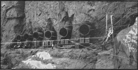
|
| Outlet Conduits for Arizona Valve House |
|
| Excavation . . . Downstream Plug Arizona Inner Tunnel |
The penstock tunnels are approximately horizontal but the construction adit drops downward a vertical distance of 45 feet from canyon wall to diversion tunnel. The penstocks and adit were excavated, the penstocks lined, and the 13-foot pipe installed in the tunnels in a manner similar to that previously described for the upper system.
Excavations of the construction adits and upper penstock header tunnels were accomplished with drilling jumbo equipment, small 1-1/4—cubic yard power shovel and 8-cubic yard trucks. The jumbo was equipped with 30 compressed air drills and a heading 41 feet wide by 36 feet high was drilled and loaded in one setup. Muck was loaded into trucks by the power shovel, hauled through the construction adit to the canyon wall, dumped into the canyon below, reloaded into trucks and hauled out of the canyon.
The inclined header tunnel from the upstream tower was excavated by driving a 7-foot by 14-foot top heading from the arch of the diversion tunnel, enlarging downward to the floor of the incline, and breaking the remaining sections into the slot thus formed, starting from the top and working downward on horizontal benches. The muck was removed from the diversion tunnel by power shovel and trucks.
The smaller tunnels were driven by usual tunnel methods, using Conway muckers and trucks where permissible.
The upper header tunnels were lined to 37-foot diameter behind circular steel forms. The concrete was mixed at the high level plant, transported by truck and cableway to construction adit portal, placed on a car hauled by a storage battery locomotive, pushed to position at the foot of an inclined belt conveyor, and carried by belt to chutes for pouring invert and sidewall or to a compressed air gun for filling the arch section. The forms were moved on short sections of centrally located track, the ends of the tracks being supported by heavy structural steel columns.
Lining for the inclined header tunnels was placed behind circular timber forms for the sections through the curves. In the straight tunnel sections, concrete was poured first in the invert beneath wooden forms, followed by lining the sidewall and arch behind the circular forms. Lining was started at the foot of the incline and progressed upward. The forms were moved by hoists and, in the straight sections, travelled on rails set on the invert lining. Concrete from the high level plant was lowered from canyon rims by 15-ton derricks to a hopper above the upper end of the incline, from where the concrete flowed through zig-zag chutes to position.
Concrete lining in the horizontal penstock tunnels and the lower portions of the inclined tunnels was placed by a concrete pump behind wooden forms. The pump was located at the canyon wall inlet of a tunnel, received its concrete via cableway from the high level plant and pumped it through a 7-inch line to the back of the forms. Concrete for the upper sections of the inclined tunnels was conveyed to forms via zig-zag chutes running downward from the penstock header tunnel.
All the penstock header and penstock pipes are installed within tunnels of sufficient size to allow inspection and maintenance.
| <<< Previous | <<< Contents>>> | Next >>> |
boulder_dam1/sec6.htm
Last Updated: 01-Feb-2008