|
GEORGE WASHINGTON MEMORIAL PARKWAY
Patowmack Canal and Locks (Great Falls Section) Historic Structures Report — Architectural Data Section |

|
IV. EXISTING CONDITIONS
WING WALL
The upper entrance into the canal from the river is located approximately 1,600 feet north of the Visitor Center. On the riverside of the inlet are the ruins of a once-extensive wing wall that was constructed ca. 1785-1787. In 1821, at a general meeting of the Patowmack Company, it was noted that there was a shortage of water at this location, and that the wing dam had been raised and extended considerably to provide more water for operations. This structure, along with the remainder of the canal, was abandoned ca. 1830. Flooding has taken its toll by reducing the wall to a bare outline of its original configuration. The existing visible remains, seen during low water periods, consist of small stone that could be handled by either one or two men. The use of this size stone indicates that construction of this wing wall (dam) may have been of wooden-timbered pens or cribs which were filled with stone that was either wheeled or carried from the shore.
The remains of the dam and vegetative growth on it indicate that it angled out into the river in a northerly direction, past the head of a low island in the river, and may have continued on another 1,000 to 1,200 feet in length. The upper elevation of this wall would have been at least as high as the operating level of the canal in order to divert additional water from the river into the canal. The surplus water would simply overflow the dam.
Mine Run flows into the canal approximately 500 feet downstream from the canal entrance. This stream drains 2-1/2 square miles of a partially wooded undeveloped area. According to the Architect/Engineer firm of Hayes, Seay, Mattern and Mattern, during low flow conditions, the Mine Run flow splits as it enters the canal, with almost two-thirds flowing north into the river and one-third flowing south to the lower spillway. This is apparently caused by sediment deposits at the mouth of Mine Run which have raised the elevation of the canal bed in this area. Flow enters the canal from the river only during moderate to high flow conditions.
UPPER GUARD GATE AND SPILLWAY
The Upper Guard Gate and Spillway is located approximately 1/4 mile north of the Visitor Center. Flooding has destroyed all evidence of the abutments on the river side of the guard gates and much of the upper portion of the berm wall. So far, no reference has been found to place the construction of the guard gate and/or spillway within the historic period. While it is possible that these two structures represent the location of historic features, the workmanship suggests major reconstruction during the early 20th century (possibly by the Civilian Conservation Corps). In any event, evidence is insufficient to determine whether the guard gate was constructed in the form of swing or mitre gates or designed as a removable dam structure, which could be installed for diversion purposes during periods of high flow and removed to permit the passage of canal traffic during normal operations.
The thickness of the masonry walls at this location bears testimony of the frequency and force of Potomac River floods. On the berm bank a heavy stone wall parallels the canal for twenty-nine feet, and then at its north end turns westward at a ninety degree angle. From this angle, it extends approximately thirty-three feet into the berm bank to resist flood water. On the riverside, below the guard gate, the canal wall is twenty feet thick and parallels the canal for 400 feet. The exterior of this wall is covered with large rubble stone, dry laid with a slight batter. The interior is dirt fill. At the south end of this feature, the wall turns eastward towards the river for some 120 feet and then turns south to where it appears to connect to the lower spillway. The space created by this offset could have been used as a holding basin or possibly a reservoir for supplying additional water to the canal and mill operation downstream.
Some of the canal bed was cut 1-3 feet deep into the bedrock. The stone walls rise from bedrock along this entire section.
On the canal side of the river wall, at the guard gate, there are a row of vertical holes in which 1-inch diameter rods may have been inserted to secure the lower row of stones in the rock wall. In one of these holes is an old rock drill positioned with its cutting edge upward.
Immediately above the guard gate and adjoining the upper end of the river gate abutments was the upper spillway. It consists of a low masonry dam, heavily flood damaged and barely visible in the bed of an old river channel on the riverside of the canal. The top elevation would have been at the normal operating level of the canal, and surplus water above this level would spill over the dam and back into the river. It was once approximately 30 feet in length.
LOWER SPILLWAY
Less than a hundred yards north of the Visitor Center, the canal has a spillway located in the river wall of the canal situated in an old river channel. The spillway is approximately 60 feet in length and its upper elevation was the normal operating level of the canal. Flooding in the late fall of 1985 did considerable damage to the remains of this structure.
At the present time there is no evidence that it was a historic feature or what function it performed. The workmanship appears to be early 20th century (possibly Civilian Conservation Corp).
CANAL PRISM
The canal prism was the navigable channel affording level stretches of water between the canal inlet, locks, and discharge points. Although the majority of the canal walls are now indistinct, they were at one time easily distinguishable. Siltation and erosion have obliterated surface traces of the canal prism over much of its length.
Archeological investigations conducted in 1977 determined that the historic canal channel was approximately 30 feet wide at the top with sloping banks, giving a 20-foot width at the bottom, and a depth of 6 feet. The canal prism was cut through bedrock in a number of locations. In other areas, the canal banks were either stabilized with riprapping on the sloping banks or dry laid stone walls were utilized to form the banks of the canal. These features can be detected along the entire length of the canal except at the entrance to the holding basin.
If additional information on the canal prism is desired, one should refer to "Archeological Test Excavation of the Patowmack Canal, Great Falls Park, Virginia" by Douglas C. Comer, October 3, 1977.
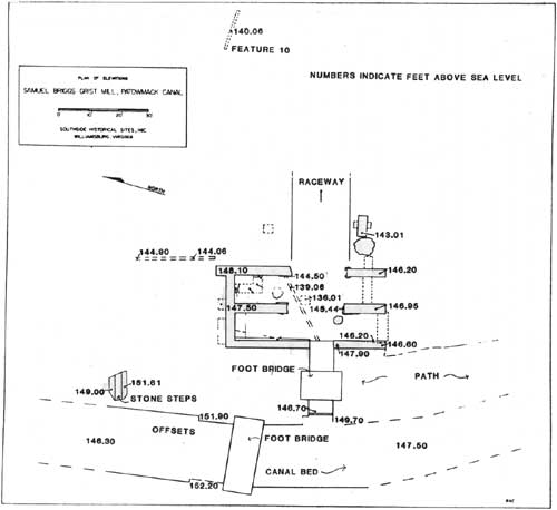
GRIST MILL SITE
Just south of the Visitor Center and adjacent to the river wall of the canal are located the ruins of an old mill. The ruins consist of the stone foundations of four chambers, with most of two adjacent chambers situated on the north and south sides of a centrally located raceway. A sluiceway, presently beneath a wooden foot bridge, connects the canal to the west with the raceway. This in turn leads to the Potomac River on the east; a pathway and possible loading area are located between the canal and mill. While an outline of the foundations protrudes above grade, each north-south wall to some degree has collapsed into the raceway. The west foundation may have been rebuilt at its higher elevations, as indicated by the stonework pattern. The overall dimensions of the structure are 27 feet (east-west) by 53 feet (north-south); the latter dimension includes the 8-foot-wide sluiceway. Each wall is 2 to 3 feet wide.
Within the canal stonework northwest of the millsite there are two offsets within the masonry walls. These offsets may represent a lock or sluice mechanism associated with controlling the water flow into the canal and/or mill. The offset on the western wall is 1 foot, six inches and the offset on the eastern wall is 1 foot, ten inches.
|
| FIGURE 1. (click on image for a PDF version) |
There is a question about the age of the existing stonework within the sluiceway. Because of the cement lining and the apparent rebuilding of the sluiceway walls, it is questionable if the location of the present sluiceway coincides with that of the original.
A cement footing, approximately 2 feet in diameter, is present within the canal fill at the entrance to the mill sluiceway. This feature may have been associated with an early 20th century structure which was built at this site.
The existing sluiceway is 8 feet wide and 22 feet, 6 inches long before it drops into the raceway. The floor is lined with cement and the bottom 1 to 2 inches of each wall are coated with cement parging. The northern face is 5 feet, 11 inches high. For the next 3 feet above the parging, the wall is patched with cement to within 8 feet, 5 inches of the raceway (the rest of the wall is unmortared). The top 1 foot, 9 inches of the wall is dry laid stone. The southern face of the sluiceway is entirely unmortared except for the base.
The stonework at the point where the sluiceway drops into the raceway is unmortared.
For more information on the mill itself, one should refer to "Samuel Briggs Grist Mill, Patowmack Canal," by Charles G. Troup, Arthur G. Barnes, and Norman F. Barka, Southside Historical Sites, Inc., c/o Department of Anthropology, College of William and Mary, Williamsburg, Virginia, January 1979 (Rev. November 1979).
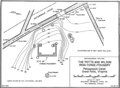
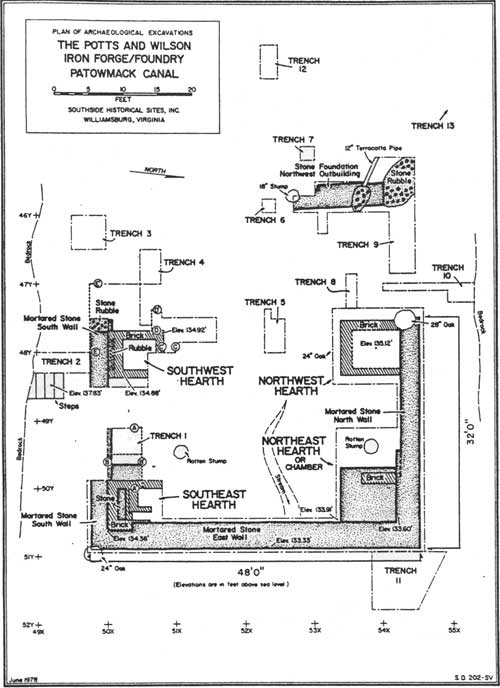
FOUNDRY SITE
Located adjacent to the east side of the river wall of the canal and approximately seven hundred feet south of the Visitor Center is the forge/foundry site. The existing gap (sluiceway?) in the river wall of the canal is stone, laid in mortar, and is non-historic. During archeological investigations made in 1977-1978 a trench, two feet in depth, was placed in the gap under the footbridge. Sterile soil was not encountered; a note was made that the fill beneath the footbridge is extensive.
There was never enough evidence recovered during the archeology work to suggest the location or nature of the water power system to the foundry, but it is assumed that there was a wooden flume used to feed water from the canal to an overshot wheel. The location of the present gap could be at or near the original location of the flume.
During the late 1970s, the remains of the forge/foundry were covered with black plastic, which in turn was covered with fill to try and protect the resource from further erosion. The flooding in 1985 has exposed sections of the plastic and much brick rubble can be seen scattered over the entire site. Details of the forge/foundry are located on the archeological site map and the plan of archeological excavations (figures 2 and 3.)
|
| FIGURE 2. (click on image for a PDF version) |
|
| FIGURE 3. (click on image for a PDF version) |
For more information on the building itself, one should consult "The Potts and Wilson Iron Forge/Foundry, Patowmack Canal", by Charles G. Troup, Arthur G. Barnes, and Norman F. Barka, Southside Historical Sites, Inc., c/o Department of Anthropology, College of William and Mary, Williamsburg, Virginia, June 2, 1978 (Rev. November 1979).
|
| FIGURE 4. (click on image for a PDF version) |
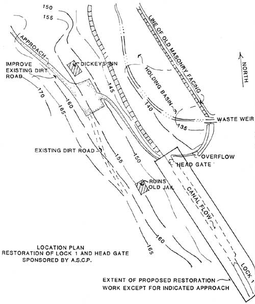
HOLDING BASIN
The holding basin functioned as a reservoir to impound sufficient water to operate the locks. Roughly triangular in form, it is estimated that the total length of the basin, from where the canal begins to widen to form it, to the head gate, is 2,400 feet. The maximum width of the basin is approximately 210 feet at the southern end. During the archeological investigations of 1977, a laid-up stone wall was found to the north of the head gate running along the west side of the basin. This wall was in line with a line of stone visible a few feet west of the west wall of the head gate. A sketch, prepared by the American Society of Civil Engineers (undated) indicates a stone wall extending along the berm side of the holding basin for the entire length of the basin. Surface traces of this wall could be found.
The eastern bank consisted of a berm and a dry-laid stone retaining wall. The top of the berm is thought to have incorporated a 12 foot wide pathway which permitted products from the grist mill and foundry sites to be transported to the holding basin for loading onto boats.
From the archeological work accomplished in 1977, it was determined that the depth of water in the holding basin at its southern limit ranged from 4 to 7 feet near the head gate and the west bank. At the center of the basin the water depth measured 10 feet, and it ranged to 12 feet at a point approximately 40 feet west of the waste weir.
WASTE WEIR
The combination waste weir/overflow is located at the southeast end of the holding basin. The structure may have been largely reconstructed after the historic period. There remains no evidence of gates or operating features.
Water from the weir flows through a natural drain towards the southeast, and then back to the river in a dogleg through a steep gorge cut into solid rock. At the point of the dogleg in the gorge, a man-made cut leads back to higher ground. The many drill holes and evidence of black powder blasting indicates that this was to be the original path of the canal. In 1795 William Weston, the English engineer of the Schuylkill and Susquehanna Canal Co. of Pennsylvania, recommended that this original path not be used.
CONTROL GATES
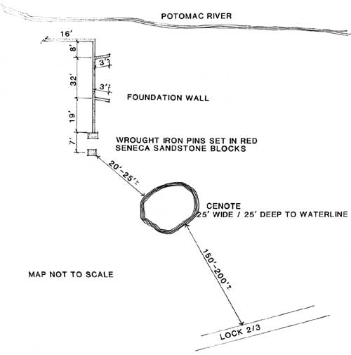
About, twenty yards due east of the head gate is another break in the holding basin wall. It is felt that this was the location of a control gate, mounted in a channel of cut stone walls 8 feet wide by 12 feet long, with wing walls extending on both ends of the channel on about a 45° angle. This gate fed water into a channel which leads to a lower holding basin. The channel parallels the canal and locks down to the head of Lock 2, and the beginning of the lower holding basin.
Located about 150 to 200 feet northeast of Lock 2 is a cenote-like sinkhole. The cenote is approximately 25 feet across and 25 feet in depth to the water line, and may continue to a great depth below this level. A modern wire ladder has been placed within the cenote (presumably for safety reasons if someone fell in). The area has been fenced off with six foot high chain link fence but the north end of the fencing has been pushed over and is creating a safety hazard. The purpose or association, if any, of the cenote to the canal is unknown.
Approximately 20 to 25 feet northeast of the sinkhole are the remains of another control gate structure. It is felt that this feature controlled the flow of water from the upper holding basin to the lower holding basin. The foundation remains consist of a large natural rock outcrop with a seneca sandstone block on top, the latter held in place by a wrought iron spike. Seven feet away another rock outcrop is present, also with a seneca sandstone block held in place with a spike.
To the east of this control gate traces of a stone wall extend over the drop off to the Potomac River and run northward. It may be that this was once the northern wall to the lower holding basin. If this were the situation, the lower basin extended from the upper end of Lock 2 to a point just below the upper lock gate of Lock 3, a distance of nearly 230 feet. Apparently the lower holding basin discharged directly into mid-lock of Lock 3 through some sort of control gate in the river wall of the lock. This area is now covered with sand, debris, and vegetation.
|
| FIGURE 5. (click on image for a PDF version) |
HEAD GATE
The head gate is located at the southwest end of the holding basin. It is also referred to as a guard gate, head lock, an inlet or outlet gate, a feeder gate, and a stop gate.
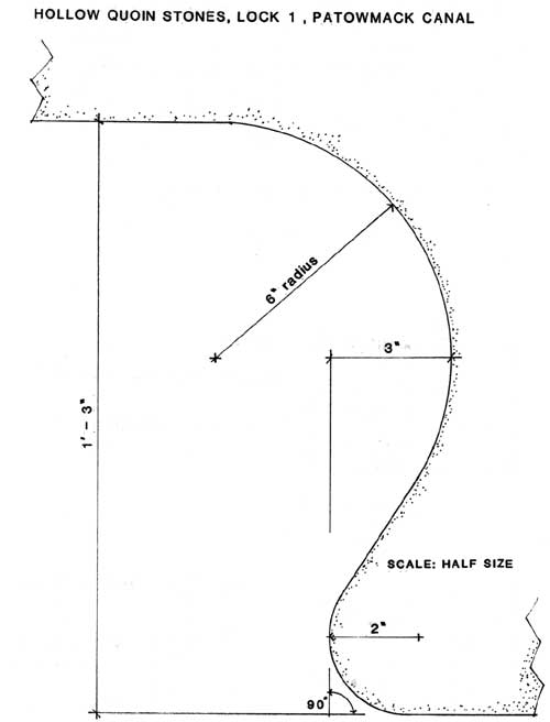
Three of the hollow quoin stones are visible in each of the walls, indicating that the gates were swing-type mitre gates. Since the head gates allowed water to pass down to the upper gates of Lock 3, they may have had wicket gates in them. The guard gates were constructed ca. 1796-1797, and they may have had sliding gates as used in Lock 1. The hollow quoin stones have an extra 4-inch deep recess in the gate pockets which might have accommodated a vertical sliding gate.
The hollow quoin stones are of well-dressed red seneca sandstone. The remains of wall down river of the quoin stones is mortared rubble stone. The total thickness of the wall in this area is 8 feet.
The hollow quoins are cut on a 6-inch radius to accommodate a gatepost of 12-inch diameter. They are quite shallow, being recessed only 1/2-inch downstream from a line perpendicular to the run of the lock. This may indicate a meeting of the mitre gates on a more obtuse angle than is usual.
The headgate channel was designed to be 14 feet in width. There has been little displacement of the stone walls as the bottom course still measures 13 feet 11-1/2 inches apart. The top two courses have moved several inches due to freeze/thaw and vegetation; this movement occurred because the two 1-inch diameter iron dowels have been removed from the copings. These coping stones were drilled vertically to tie the stones together and prevent shifting on their bed planes.
Both of the hollow quoin coping stones rest in a recess cut into the second course of stones to help resist the downstream force of the mitre gates. The hollow quoin coping stones measure 4 feet by 4 feet by 1 foot 4 inches. On the berm side, the second course of stone is 1 foot, 1 inch thick under the coping stone and 1 foot, 1 inch thick downstream of the coping, thus providing a shoulder 6 inches high and 1 foot, 2 inches wide to act as a thrust block for the coping.
On the riverside, the second course of quoin stones is 1 foot, 2 inches thick under the coping and 1 foot, 7 inches thick on the downstream side of the coping, creating a shoulder 5 inches high and 7 inches wide to back up the coping.
Below the hollow quoins, the back-up walls extend on the line of the gates 14 feet apart. The berm wall continues about 100 yards to Lock 1 in a nearly straight line. The river wall extends parallel to the berm wall for about 20 feet below the gate quoins, and then curves back toward the river for some 6 feet in 12 feet of run, and then straightens out and runs parallel to the berm wall approximately 20 feet from it.
For approximately 20 feet downstream of the guard gates, the lower levels of the wall are faced with cut red seneca sandstone.
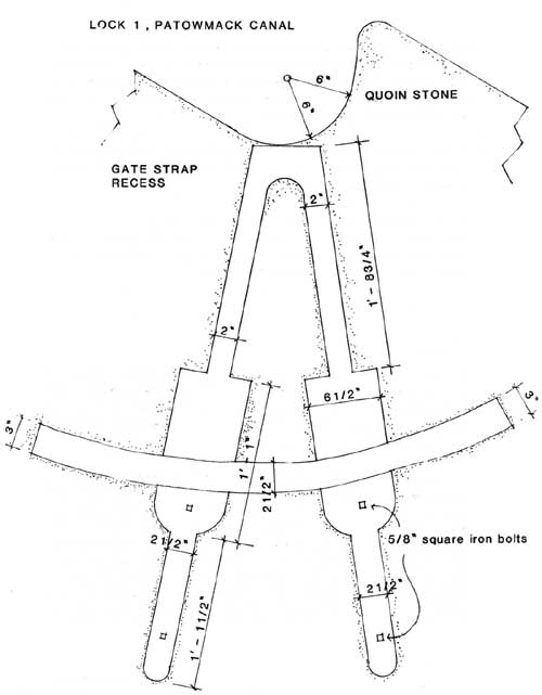
The gate straps are missing from the hollow quoin coping stones, but they were fully let into the stones and the recesses indicate their shape and size.
The gate straps seem to have been of the slotted "L" type. Each strap was held down with two bolts. Those on the berm wall are 1-inch diameter iron bolts with nuts, while those on the river wall were 1-inch square bolts set in 1-inch square holes.
On the berm wall the gate straps seem to have been 2-3/4 inches wide by 1-1/4 inch thick. The non-working ends were not turned down and let into the stone as is common on other canals. The upstream recess for the strap is 2 feet, 3-1/2 inches in length while the downstream recess is 2 feet. One of the four hold-down bolts is missing on the berm coping. Probing showed that the hole was bored a full 1 inch in diameter and 5-1/4 inches into the stone.
The gate straps on the riverside, similar to those on the berm wall, were fully recessed into the stone and did not turn down at the ends. The downstream strap seems to have measured 3 inches in width on the working end to 2-1/2 inches wide on the non-working end and 2 to 2-1/2 feet in length. The upstream strap varies from 3 inches in width on the working end to 2-3/4 inches wide on the other end. Both straps seem to have been 1-1/2 inches thick on the working end and about 1-3/8 inch on the other end. The upstream strap was 2 feet, 3 inches in recessed length.
There was seemingly much use of flat strap iron cramps with turned down ends fulled recessed into the stones. They were installed both in the stone courses below the copings as well as the copings themselves. The cramps were approximately 8 inches in length with turned down ends recessed about 1-1/2" inch into the stone. Most are of 1/2 inch thick stock, 1 to 1-1/4 inch wide, and set back from 2 to 4 inches from the face of the stone.
The hollow quoin coping on the river wall appears to be somewhat newer and is not cut quite the same as its counterpart in the hollow quoin. It could be that this stone was a historic replacement.
LOCK 1
The uppermost (northern) of the five locks constructed by the Patowmack Company is generally referred to as Lock 1, though this may not be the historic numbering system.
Although much distorted by time, freeze/thaw, and vegetation, Lock 1 measures 14 feet in width by 101 feet in length. It was designed for a lift of 10 feet and a capacity of 18,200 cubic feet of water.
This lock appears to differ from the other locks in this section in that each wooden lock gate may have had a sliding wicket gate which opened and closed vertically by some sort of rack and pinion device. The device would have been mounted on the upstream side of each wooden gate. Both the rack on the gear train and the wicket gate frame would have made the lock gates thicker than the gate pocket depth of 1 to 3 inches. Additional recesses are necessary to accommodate both the wicket gate mounting and the gear train when the lock gates were open and tight against the gate pocket walls. As none of the other locks, in this section have their original gate pockets, it is unknown whether this detail was typical throughout the site.
The gear train recess runs vertically through the gate pockets, 5 inches wide and 5 inches in depth. The edges of the stone adjoining this recess in the upper gate pockets were beveled on a 45° angle, 1 inch in width, though this was not done in the lower gate pockets. The lift gate recess measures 8 inches in depth by 4 feet in width by 5 feet, 2-1/4 inches in height, measured from the top of the mitre sill. The edges of the stone adjoining the lift gate recess were also beveled on a 45° angle, for 1-1/4 inch in width in the upper gate pockets, though not in the lower ones.
The top of the coping stones measured 7 feet, 1-1/4 inch above the top of the mitre sill. The hollow quoin coping stones of the upper gates measured 1 foot, 10-1/2 inches in thickness on the riverside and 1 foot, 11 inches thick on the berm side. The hollow quoins were cut on a 6-inch radius which would indicate the use of 12-inch diameter gateposts.
The elevation of the remainder of the lock below the upper gate pockets was almost exactly at the bottom of the coping stones on the upper gate pockets or 5 feet, 2 inches above the mitre sill. Thus this lock has the appearance of a guard lock for high water periods, and the upper gates seem to have been nearly 2 feet higher in elevation than the lower gates of the lock.
Stone coursing varies slightly in that the riverside wall quoin stones were measured as follows: coping, 1 foot, 10-1/2 inches; 2nd course, 1 foot, 4-1/2 inches; 3rd, 1 foot, 2 inches; 4th, 1 foot, 2-1/2 inches; 5th, 1 foot, 6 inches; 6th, 1 foot; 7th, 1 foot, 1 inch; 8th; 1 foot, 6 inches. On the berm side the coping was 1 foot, 11 inches; 2nd course, 1 foot, 3-1/2 inches; 3rd, 1 foot, 2 inches; 4th, 1 foot, 3 inches; 5th, 1 foot, 6 inches; 6th, 1 foot; 7th, 1 foot, 1 inch; and 8th, 1 foot, 6 inches.
Upstream of the hollow quoin stones, two courses (11 inches and 1 foot in thickness) are substituted for the 1 foot, 11 inches-thick quoin stone.
Lock 1 has a unique breast wall. Both the upstream and downstream vertical faces were cut in an arc. The downstream face seems to be cut on a radius of about 10 feet, while the upstream face of the breast wall seems to have been cut on about a 28-foot radius.
The upper course is the only one in view, and consists of four stones of approximately equal length and 1 foot, 6 inches in thickness. The two end stones are recessed into the lock walls some 1 foot, 1 inch. At their juncture with the lock walls, these two end stones measure 3 foot, 9-1/2 inches from the upstream face to the downstream face, while at midpoint between the lock walls the breast wall measures only 2 feet, 1-1/2 inch between faces.
A recess of 8-1/2 inches in depth was cut into the breast wall to receive the lower chord of the mitre sill. The mitre sill appears to have been 1 foot, 3-1/2 inches in depth (vertical thickness) and the upper 7 inches above the breast wall may be from the putlocks left in the wall.
The wooden mitre sill appears to have had a rise of about 3 feet, 8 inches measured from the downstream face of the lower chord to the apex of the two upper chords.
The entire floor of the upper gate pockets is paved with stone to the bottom of the mitre sill for some 4 feet, 11 inches above the downstream face of the lower chord. Apparently these stones were not smooth for they were covered with a lime-sand mortar to form a perfectly smooth bed for the mitre sill.
Where the downstream face of the breast wall meets the upper surface of the wall, this edge is beveled on a 45° angle for 2-1/2 inches in width. Although the lock walls are out of plumb, they are still 13 feet, 11-1/2 inches apart at the breast wall, only 1/2-inch distortion from the original 14-foot design width.
Above the upper gate the lock walls extend 1 foot, 6 inches along the line of the lock. The berm wall remains appear original in their lower levels, and appear to bend back into the berm bank in a turn of unknown radius. The exposed wing and turn of the river wall above the upper extension walls is built with native rubble stone and does not disclose its original form.
The upper gate pocket is 9 feet, 10-1/2 inches wide by 1 foot, 3 inches deep. It is 10 feet between gate pockets. The lower gate pockets are 10 feet, 2-1/2 inches in length. Below the lower gate pockets, the lower river lock wall extends horizontally approximately 16 feet and then steps down some 10 feet in vertical height and becomes a native stone, rubble wall which swings east some 6 feet in about 12 feet of run. The end section of the lock wall was restored under a construction contract awarded in 1978. The berm wall of the lock has collapsed below the lower gate pocket, but appears to have been built from native rubble stone which continued on the same line as the lock wall. As elsewhere, the expansion in width of the canal below the lock, from the 14 feet width of the lock to the 20 feet width of the canal, was done at the expense of the river wall, while the berm wall of the canal is aligned with the berm wall of the lock.
The lock walls are built mainly with dressed red seneca sandstone with a mixture of freestone, micashist and occasionally a granite. The backup walls are of rubble stone native to the area that is possibly the product of blasting in the construction of the canal. The sandstone is laid with butt joints and it is surmised that a lime/sand mortar was used as a setting bed, and at vertical joints, but it has all but deteriorated with time. The rubble stone back-up was definitely laid up in a lime/sand mortar mix that, though much deteriorated, is still quite evident.
Both upper lock pockets, upper extension walls, turns, and wing walls are much distorted and in various stages of deterioration. A large number of coping stones on the river wall of the lock have fallen, and the remainder of the wall is in fair condition. The berm wall is also in fair condition, the lower end section south of the lock pocket having been relaid in rubble stone in 1978-1979. Also during construction activities in 1978-1979, the lock was partially excavated to help drain both surface and ground water. The sandstone that was exposed to the elements now seems to be deteriorating at an accelerated pace. Pipe bracing was introduced at this same period at the gate pockets, in the hopes of halting any further movement of the walls in these locations.
There has been an attempt to replace missing stone in the lock walls. Patches have included brick and mortar, cement, and mortar either flush with the face of the wall or recessed. All of these patches appear to be of mid-twentieth century materials and craftsmanship. The recessed patches are attributed to the 1978-1979 construction project.
Most of the header stones in the lock walls seem to be square, with their length equal to their height in the course. These headers appear to have been more closely spaced in the thinner courses. Several headers are still in bond as evidenced by their being recessed beyond the plane of the stretchers.
There is little evidence of the use of iron cramps in the lock walls except around the gate pockets. In many of the courses, at the gate pockets below the coping stones, there was considerable use of flat strap iron cramps. Judging from the recesses in the stones, the iron cramps seem to have been of 1/2-inch thick stock, from 1 inch to 1-1/2 inch in width, and from 7 inches to 1 foot in overall length. The ends of the cramps were turned down, and the cramps were fully let into the stone and leaded in.
All of the gate straps were missing. The recesses in the stone give no hint of the method by which they were secured to the gate post collar.

|
| FIGURE 6. (click on image for a PDF version) |
|
| FIGURE 7. (click on image for a PDF version) |
|
| FIGURE 8. (click on image for a PDF version) |
On the berm lock wall at approximately midlock there is one section of the wall that is faced with rough cut, random coursed native stone. This section is about 15 feet in length and goes down through the eighth course. This may have been one of many repairs made to the locks during its historic operating period.
At the river wall, below the upper gate pockets, the first two courses of stone are rough cut native stone. Nearly all of the coping stones are missing on the river side.
It was noted that three of the cut red seneca sandstones in this lock were inscribed with a stonecutter's mark. All of the stones bear the same mark but the length of the mark varies with the thickness of the stone. This same marking also appears at Lock 2.
LOCK 2
The river lock wall is in ruin above the upper gate quoins. The upper wing walls are only visible on the berm wall where the upper extension walls extend about 6 feet above the lock pockets, turn sharply, and extend approximately 10 feet into the bank with a gain of about 6 feet in the direction of the run of the lock.
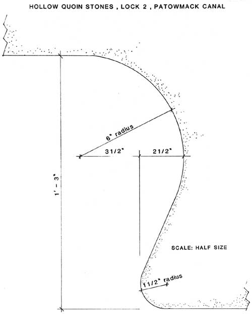
The upper gate pockets were 1 foot, 3 inches in depth. Their length cannot be measured, but was probably the same as the lower gate pockets. There are only four courses of stone above the upper mitre sill. The hollow quoins are cut on a 6-inch radius for a 12-inch diameter gatepost, and the reverse curve is cut on a 1-1/2 inch radius. The reverse curve refers to where the tangent of the gatepost hollow turns to meet the inner wall of the midlock section. The hollow quoin is cut into the quoin stones, 2-1/2 inches deep taken from a line perpendicular to the run of the lock and flush with the reverse curve.
There are no extra recesses in the gate pocket walls. This would seem to indicate that this lock had a butterfly type of wicket gate mounted in the lock gates rather than lift gates as in Lock 1.
The breast wall is of rough cut, rough faced native stone. The downstream face was flush with the downstream face of the upper mitre sill. It is badly bulged and about 3 feet, 6 inches lower in the center than its original height.
Approximately 30 feet of the upper end of the berm wall has collapsed below the breast wall. The berm wall of the lock was built of native stone that was probably blasted by the canal construction.
Iron strap cramp recesses indicate that the cut stones in all gate pockets were cramped with 1/2 inch by 1-1/2 inch flat bar stock from 8 to 10 inches long, and fully let into the stones. The turned down ends penetrated into the stone from 5/8 inch to as much as 1-3/4 inch below the bed of the cramp.
The coping stone of the upper gate quoin on the river wall is intact, though out of place by about 2 feet down river. It measures 1 foot, 2 inches in thickness as does the course below it. The third course of stone is 10 inches, and the fourth is 1 foot thick and rests on top of the upper mitre sill. Thus the top of the coping was only 4 feet, 2 inches above the top of the mitre sill.
Below the upper gate pockets, the coping stones of the river wall are of native stone. Except for a stretch of about 16 feet, the rest of the river wall is of cut stone, mostly red sandstone with some freestone. All quoins and gate pockets are of freestone. The use of flat iron cramps with turned down ends is found in each successive course at the pockets. The coping stones on the river wall show additional reinforcing with vertical iron dowels of about 1-inch diameter bored through the coping and well into the course below.
Coping stones on the berm wall have two, three, and even four dowels per stone set vertically through the copings and into the lower courses of stone.
The tie stones or headers are closely spaced in the river wall between gate pockets. All of the identifiable headers are quite narrow in length, some as short as 4 inches, with most being 6 to 10 inches long.
The berm wall appears to have been cut from solid rock and then faced with native stone. This wall has collapsed from the upper end of the lower gate pocket through the hollow quoins and completely hides all traces of wall for about 7 feet below the lower gate pocket. The wall then appears again fairly substantial and continues on the line of the lock in a roughly coursed, rough laid wall of native stone. This wall is battered about 1 foot in 4 feet of vertical height for a distance of some 110 feet. Flooding during the fall of 1985 created a large void and belly at the base of this wall at the north end.
The lower gate pocket of the river wall was rebuilt in 1978-1979, but the downstream wall was left in a precarious state of deterioration. A temporary bracing system was installed at this location in 1978-1979 to try to prevent any further movement of the wall. At this location, the native rubble stone back-up wall is clearly exposed. Traces of sand/lime mortar remain, but most has been leached away by water. The face stones in this gate pocket are thin, some being only 6 to 7 inches thick.
From the lower end of the lower gate pocket on the river wall of the lock, the lower extension wall extends on the line of the lock about 16 feet and then seemingly tapers down while angling toward the river. Here, the wall has collapsed and hides all traces below a point about 12 feet below the lower pocket. As with the berm side, the river side wall appears again in a roughly coursed, rough laid stone wall. The canal bed in this area widens to about 16 feet, 6 inches, with the extra width made up on the river bank wall, while the berm side continues on line with the lock walls.
The only extant section of cut stone on the berm wall is located immediately above the lower gate pocket. It compares roughly with the coursing on the river wall and measures as follows: bottom course covered; 2nd course: 1 foot; 3rd: 1 foot; 4th and 5th: 1 foot, 1 inch; 6th: 1 foot, 2 inches; 7th: 1 foot, 1 inch; 8th and 9th: 10 inches; 10th: 11 inches; 11th: 1 foot; 12th: 11 inches; 13th: 1 foot; 14th: 1 foot, 2 inches; 15th: 1 foot, 2 inches; 16th or coping stone is missing. Although there are course thickness variations in nine of the courses from those of the river wall, the total height appears to have been the same.
The bottom course of stone on the river wall of the lock rests on rubble stone brought up from bedrock to form an even bed. It measures 11 inches in thickness. The 2nd course is 1 foot thick; 3rd: 1 foot; 4th: 1 foot, 1 inch; 5th: 1 foot, 2 inches; 6th: 11 inches; 7th: 1 foot; 8th: 11 inches; 9th: 1 foot; 10th: 10 inches; 11th: 1 foot, 1 inch; 12th: 10 inches; 13th: 1 foot, 1 inch; 14th: 1 foot, 2 inches; 15th: 1 foot, 2 inches; 16th: 1 foot, 2 inches, for a total of 16 feet, 4 inches.
The quoin coping stone of the lower gate pocket on the river wall shows no sign that the gate straps were recessed into the stone. Rather, they seem to have been similar to those on the upper gate pocket and held down with one 1-inch bolt. One of the bolts is in place, but no sign of the gate straps exists.
An unusual feature of this lock is the numbering in Roman numerals of the hollow and half-hollow quoin stones. They are numbered from the bottom, and the numbering is visible on the third, fourth, ninth, tenth, thirteenth, and sixteenth courses from the bottom. The sixteenth course is the coping stone, and is at the same elevation as the coping of the upper gate pocket.
The lock measures 88 feet, 7 inches between gate pockets. The lower gate pocket is 9 feet, 2-1/2 inches in length and 1 to 3 feet deep.
|
| FIGURE 9. (click on image for a PDF version) |
Near the middle of the lock, two very interesting stones lie behind the copings. They are of different lengths but each is 4 feet wide. Their outer edges have been recessed about 1/2 inch to hold planking. It is felt that the stones and planking may have supported an incline plane which was used to transport cargo over the gorge section ca. 1797 and before the locks were fully operational.
There are several dozen stones in the lock walls which bear stonecutters' marks. Although erosion of the stone makes them difficult to decipher, some thirteen different marks have been identified and all but two are in the freestone. An interesting side note is that one of the marks located at the canal locks matches the marking of a stone from the White House.
LOCKS 3, 4, AND 5
Locks 3, 4, and 5 formed a staircase of locks, the lowest gate of Lock 3 being the upper gate of Lock 4 and the lower gate of Lock 4 being the upper gate of Lock 5.
The ravages of time, floods, and vegetation have destroyed most of the identity of this staircase section, and debris covers much of the remains except for the slash of the gorge section. When one considers that the gorge section was blasted with black powder placed in hand-drilled holes, it was indeed a remarkable engineering feat for those times.
Lock 3 was a unique structure. At its lower gate, it was 12 feet in width, while just below the upper gate it was much wider, for it was in this lock that the boats changed direction by 18 degrees, from N. 32°W., above Lock 3 to the course of N. 50°W. of the gorge itself.
Above the lower gate of Lock 3, the berm wall is of roughly cut, coursed stone at a bearing of about N.50°W. for a distance of approximately 88 feet. Seneca, freestone, granite and native schist with a reddish mortar are found in this wall. The southern end of this wall was rebuilt ca. 1978 in order to keep the wall from coming apart. The river wall of the lock continues upstream above the lower gate at an angle of about N. 32°W.
The lower three gates of Locks 3, 4, and 5 were separated from each other by about 94 feet, as near as can be judged by traces on the natural stone walls of the gorge, while the two gates of Lock 3 seem to have been about 111 feet apart. Flood waters scouring through the gorge have left little of any man-made structures, except for drill holes in the rock, iron bolts of 1 inch or more in diameter, lime mortar stains, and other fragmentary evidence.
The gorge wall in Lock 5 bears slight evidence of the extensive masonry wall which once topped the natural rock outcrop on the riverside wall of the lock in order to achieve the 20 foot lift of this lock above low river water levels. It is probable that this river wall stepped up in steps of about 1 foot in elevation in 4 to 6 feet of run in order to provide easy access from gate to gate. It is also assumed that the natural rock outcrops below the lower gates on the river side were raised by a heavy masonry wall which continued out into the edge of the river some 80 feet or so. This wall gave some protection to boats entering the river at an angle to its flow. A row of horizontal bolt holes and bolts in the berm wall below the lowest gates bear indication of the possible location of horizontal boat fenders just above the waterline which would have protected a boat from the jagged rock while lining it up with the flow of the river.
Little evidence exists on the exact location of the lower gates of Lock 5. From the topography and the sheerness of the rock wall on the berm side, it seems quite evident that this gate could not be opened by the usual balance beam. Rather, it may have been opened by some sort of windlass located at a low spot on the berm wall near mid-lock and closed from some point near the sister gate on the river wall.
This location of the upper gates of Lock 5 (the lower gates of Lock 4) is marked by a notch in the natural rock face of the lower levels of the lock, and by an additional cut stone platform of five course of red seneca sandstone which is laid on top of the berm wall. It is felt that this structure acted as a platform for the movement of a balance beam.
The location of the upper gates of Lock 4 (the lower gates of Lock 3) is based on fragmentary evidence. At the berm wall remains include putlocks cut in the wall for bracing, lime wash of a once-vertical masonry structure to brace the hollow quoins, and numerous bolts and bolt holes in both lock walls. The masonry walls that once topped the natural rock of both lock walls at this point have been swept away by flooding. Above this point, the natural rock outcrop of both banks lowers in an old river channel. Both walls of Lock 3 are laid-up walls. They consist of well laid, vertical stone wall, of rough cut and random coursed stone. A large portion of the river wall of Lock 3 is covered with flood-borne river sand.
The exact location of the upper gate of Lock 3 cannot be accurately determined. Logic implies that it was located immediately north of the intersection where the sharp bend in the upper berm wall of Lock 3 converges with the southern end of the lower berm wall of Lock 2. The entire area is scoured by floods and covered with sand. If this conjecture is true, then there is only a little over 100 feet of canal between the upper gates of Lock 3 and the lower gates of Lock 2.
Immediately adjacent to the river wall of Lock 3 was the lower end of the lower collecting basin. Water in this basin was fed into Lock 3 through some sort of control gate located in the river wall of the lock.

|
| FIGURE 10. (click on image for a PDF version) |
| <<< Previous | <<< Contents>>> | Next >>> |
patowmack_canal_hsr/sec4.htm
Last Updated: 17-June-2011