.gif)
|
Man in Space
A National Historic Landmark Theme Study |

|
|
National Advisory Committee for Aeronautics Wind Tunnels |

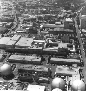
Exterior view of the Unitary Plan Wind Tunnel (in the center of the photograph), 1984.
(Courtesy of NASA, NASA/Ames Research Center Facilities Office)
Unitary Plan Wind Tunnel
| Name: | Unitary Plan Wind Tunnel (Unitary Plan Facility) |
| Location: | Ames Research Center, Moffett Field, California |
| Owner: | National Aeronautics and Space Administration (NASA) |
| Condition: | Excellent, original site |
| Builder/Architect: | NACA |
| Dates: | 1955-Present |
DESCRIPTION
Unitary Plan Facility
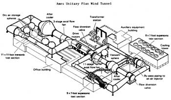
The Unitary Plan Facility is a unique system of wind tunnels comprised of three test sections: an 11-by 11-Foot Transonic Tunnel (Mach 0.40 to 1.40), a 9-by 7-Foot Supersonic Tunnel (Mach 1.55 to 2.50), and an 8-by 7-Foot Supersonic Tunnel (Mach 2.45 to 3.45), all capable of operating at variable stagnation pressures. The major common element of the tunnel complex is its drive system, consisting of four intercoupled electric motors that can provide 134.23 MW (180,000 hp) continuously. [1]
11-by 11-foot Transonic Wind Tunnel
The 11-by 11-Foot Transonic Wind Tunnel is a closed-return, variable density tunnel with a fixed geometry, ventilated throat, and a single-jack flexible nozzle. Airflow is produced by a three-stage, axial-flow compressor powered by four wound-rotor variable-speed, induction motors. For conventional steady-state tests, models are generally supported on a sting. Internal strain-gage balances are used to measure forces and moments. A schlieren system is available for studying flow patterns, either by direct viewing or by photographs, as well as a system for obtaining 51 X 101 cm (20 X 40 in.) shadowgraph negatives. [2]
9-by 7-foot Supersonic Wind Tunnel
The 9-by 7-Foot Supersonic Wind Tunnel is a closed-return, variable-density tunnel equipped with an asymmetric, sliding-block nozzle. The test section Mach number can be varied by translating, in the streamwise direction, the fixed contour block that forms the floor of the nozzle. Airflow is produced by an 11-stage, axial-flow compressor powered by four variable-speed, wound-rotor, induction motors. For conventional, steady-state tests, models are generally supported on a sting. Internal strain-gage balances are used to measure forces and moments. A schlieren system is available for studying flow patterns, either by direct viewing or by photographs, as well as a system for obtaining 51 X 51 cm (20 X 20 in.) shadowgraph negatives. [3]
8-by 7-foot Supersonic Wind Tunnel
The 8-by 7-Foot Supersonic Wind Tunnel is a closed-return, variable-density tunnel equipped with a symmetrical, flexible-wall throat (the side walls are positioned by a series of jacks operated by hydraulic motors). The upper and lower surfaces are fixed. Airflow is produced by an 11-stage, axial-flow compressor powered by four variable-speed, wound-rotor induction motors. For conventional, steady-state tests, models are generally supported on a sting. Internal strain-gage balances are used to measure forces and moments. A schlieren system is available for studying flow patterns, either by direct viewing or by photographs, as well as a system for obtaining 51 X 51 cm (20 X 20 in.) shadowgraph negatives. [4]
STATEMENT OF SIGNIFICANCE
The Ames Unitary Plan Wind Tunnel is significant because it represents the continual development of superior technical aeronautical research facilities after the end of the Second World War. These research facilities formed the foundation upon which the National Aeronautics and Space Administration would draw in 1958 to launch the American effort to land a man on the moon.
Since the construction of the Variable Density Wind Tunnel at Langley in 1921 the National Advisory Committee on Aeronautics (NACA) had built an impressive variety of technical research facilities upon which the American aircraft industry was based. These technical facilities had enabled the American aircraft industry to produce the airplanes that dominated the skys in both commercial and military applications. By 1945 the American lead in this field seemed to be evaporating. The technological achievements of the German missiles and jet aircraft indicated a lag in American aeronautical research. To assume technological leadership, the Federal Government proposed a coordinated national plan of facility construction that would encompass not only NACA, but the Air Force, industry, and universities as well. This plan, known as the Unitary Plan Act, passed Congress on October 27, 1949, and resulted in the construction of an entire new series of wind tunnel complexes to support the American Aircraft industry. [5]
The Ames Unitary Plan Wind Tunnel Complex was a product of this legislation. Construction of the facility began in 1950-1951 and lasted until 1955. Because no one wind tunnel could meet all of the demands for additional research facilities simulating the entire range of aircraft and missile flight, NACA chose to build the Ames tunnel with three separate test sections drawing power from a common centralized power plan. The transonic test section spanned 11 x 11 feet, while the two supersonic sections were smaller: 9 x 7 feet and 8 x 7 feet. Giant valves 20 feet in diameter supplied air from one supersonic leg to another. [6]
The American west coast aircraft industry quickly capitalized on the Ames Unitary Plan Wind Tunnel Complex. The famed Boeing fleet of commercial transports and the Douglas DC-8, DC-9, and DC-10 were all tested here. In addition such military aircraft as the F-111 fighter, the C-5A transport and the B-1 bomber were tested. In addition to aircraft, in the 1960s and 1970s almost all NASA manned space vehicles including the Space Shuttle were tested in the Ames Unitary Plan Wind tunnel complex. [7]
The Ames Unitary Plan Wind Tunnel Complex is a landmark in the development of conventional wind tunnels and represents the continuing effort of the National Advisory Committee on Aeronautics to provide the American Aircraft and Aerospace industries with the best research facilities possible to insure the technological superiority of the industry. It provides the logical crossover point from NACA to NASA and has contributed equally to both the development of advanced American aircraft and manned spacecraft.
FOOTNOTES
1. Ames Research Facilities Handbook (Moffett Field, California: National Aeronautics and Space Administration, 1982), p. 14.
5. Donald D. Baals and William R. Corliss, Wind Tunnels of NASA (Washington, D.C.: National Aeronautics and Space Administration, 1981), pp. 66-67.
BIBLIOGRAPHY
Ames Research Facilities Handbook. Moffett Field, California: National Aeronautics and Space Administration, 1982.
Baals, Donald D., and Corliss, William R. Wind Tunnels of NASA. Washington, D.C.: National Aeronautics and Space Administration, 1981.
Hartman, Edwin P. Adventures in Research: A History of Ames Research Center 1940-1965. Washington, D.C.: National Aeronautics and Space Administration, 1970.
Technical Facilities Catalog Vol. I Washington, D.C.: National Aeronautics and Space Administration, 1974.
PHOTOGRAPHS

Diagram of Unitary Plan Wind Tunnel
(Source: Wind Tunnels of NASA, Baals)
Last Modified: Mon, Jan 8 2001 10:00:00 am PDT
man-in-space/space4.htm

 Top
Top