|
OLYMPIC
Lake Crescent Lodge Historic Structures Report |

|
III. DESCRIPTION OF EXISTING SITE AND BUILDING FEATURES
SITE
The grounds of Lake Crescent Lodge have several remnant landscape materials and structures that survive in form, material, and intent from the original layout of the grounds. The overall spatial organization of the site remains intact. The grounds slope approximately six percent from Highway 101 down to the lakefront, some 400 feet north. Primary vehicular access to the site is off Highway 101 with major parking at the end of a short access road that ends directly behind lakefront cottages numbers 676 through 680. Additional parking is provided behind cabins 668-674 for overnight guests. The site is provided with relatively new water and sewage utility services. Much of the electrical service equipment on site is outdated and needs replacement.
Many of the original plant materials remain on the site, though many are decayed or in poor condition because of neglect. While some new plant materials have been incorporated over the years, the original structure of planting areas and massing has been maintained.
As a whole, the complex displays relationships and fundamental patterns of land use, circulation systems, building clusters and use that have remained consistent through time without significant spatial alteration. The original site design provided a variety of experiences for the visitor. In a very small area the guest had a range of spatial experiences from very public spaces—the entry path and front lawn—to semi-private areas in front of the individual cabins, to very private areas on the porches of the cabins and the cabins themselves. This pattern and gradation of spaces is still evident and contributes much to the experiential quality of the site today. In addition, most landscape and structural elements considered primary to the character of the complex are intact, including the entry and parking areas, path, building clusters and vegetation. Finally, it is evident that the lodge and surrounding components provide a special link to the past. There is a continuity and ambience that creates a quality and sense of place and sets the complex apart from similar resort developments.

|
| Figure 13. View of Lake Crescent Lodge from the shoreline. Photograph by Marty Stupich, NPS, 1983. |

|
| Figure 14. Front entry facade (east elevation) Lake Crescent Lodge. Photograph by Marty Stupich, NPS, 1983. |
LAKE CRESCENT LODGE
Structural System
The foundation of the lodge consists of 6 x 6 wood posts atop one-foot square pre-cast concrete pads. Many of the posts have wood shims possibly indicating earlier re-leveling attempts. One post, now laying prone on the ground, should be repositioned under a beam splice near the stone fireplace. Some of the posts under the later addition of the lodge are raised from the concrete pads. In general, the posts appear to be in good condition with little or no evidence of insect rot or decay. Crawl space headroom from one foot to two feet is found throughout the original building and later additions. Less crawl space is found under the existing dining room and kitchen, although access panels through the floors service mechanical spaces.
Spot elevations taken on the first floor indicate considerable settlement. Using the stone fireplace hearth as a control point, the following settlements of the main lobby were observed:
NE corner - 4 inches
SE corner - 5 inches
SW corner - 6 inches
NW corner - 4 inches
With the same control point, the following settlement of the dining room area was observed:
NE corner - 3 inches
SE corner - 0.2 inch
SW corner - 3 inches
NW corner - 0.1 inch
In the tavern area, using the brick fireplace hearth as a control point (3 inches lower than the stone fireplace hearth), the following settlements occurred:
NE corner - 1 inch
SE corner - 4 inches
SW corner - 0 inches
It should be remembered that all three of these portions tested for settlement were built at different times. A certain amount of settlement under these conditions is not unusual and would be acceptable.
The National Park Service commissioned preliminary drawings and specifications for corrective foundation work at the lodge by Systems Architects Engineers, Incorporated (SAE) of Seattle (drawing file no. 149-80020, Olympic National Park). The work was never executed due to funding shortages. Some of the work proposed by Systems Architects Engineers will need to be reviewed in the context of current conditions at the lodge before being incorporated into the rehabilitation proposal now under consideration; however, it appears that the requirements for stabilizing the original and 1950s addition foundations will have changed very little in the intervening years. This report concurs with a recommendation of the Denver Service Center that a perimeter concrete stem wall with spread footings be substituted for the strip footing with eight-inch diameter concrete columns recommended by SAE. Continuing this stern wall around the portions of the lodge to be retained will provide an enclosed crawl space capable of being insulated, while also providing for lateral shear transfer from walls to footings.
Wall framing in the historic Singer's Tavern portion of the lodge is 2 x 6 wood frame construction 24 inches on center. Wall construction of the remaining portions of the lodge is 2 x 4s construction at 24 inches on center.
The roof structure of the original lodge portion is made up of 2 x 6 rough sawn lumber at 24 inches on center. The roof has a two foot overhang with a 1 x 6 open soffit. Two by six columns have been added in the attic to brace the rafters. A structural evaluation of the roof was part of the Systems Architects Engineers' preliminary report, which recommended adding structural members to reduce rafter spans both in the original lodge portion and the later dining room addition.
Aside from the noticeable foundation settlement, the first floor appears to be in good condition. Gaps found around the windows and the porch off the main lobby can be attributed to foundation settlement. The stone fireplace has severely cracked, starting at the right corner of the opening. This is probably due to loads imposed at the beam pockets from the perimeter beams below, and to the expansion of the steel lintel of the opening.
The condition of the additions housing the kitchen, support areas and the dining room is marginal. Problems with the roofing systems over these areas were addressed in the Systems Architects Engineers' report mentioned earlier. The floor systems in these areas are wood frame with concrete topping. They have deteriorated considerably due to settlement and poor maintenance over the years.
No structural problems of immediate concern were found on the second floor of the lodge. As with the first floor, windows and doors are racked from foundation settlement. It should be noted that the attic floor joists (second floor ceiling joists) are lapped over the hallway walls below, with the joists lapping over alternate walls. Therefore, both hallway walls are bearing walls. Room partitions are non-bearing.
As in the first and second floors, windows in the attic story are racked due to foundation settlement.

|
| Figure 15. Southwest corner Lake Crescent Lodge. Photograph by Marty Stupich, NPS, 1983. |

|
| Figure 16. South facade Lake Crescenet Lodge. Photograph by Marty Stupich, NPS, 1983. |
Building Exterior
The exterior skin of the building is painted cedar shingles over 1 x 8 shiplap sheathing. A cedar shingle roof with metal flashing is laid over a 1 x 6 roof deck eight inches on center. Wood gutters are found on the original lodge portion with metal gutters on other portions of the building. The entire roof system is in poor condition and in need of major repair and replacement. The perimeter wood foundation skirting shows signs of deterioration, particularly where it is in contact with the soil, and will require major repair and/or replacement.
Some minor exterior problems at the facility are listed below; they were noted during recent inspections on site. The list should not be considered comprehensive, but more a sampling of general maintenance and repair concerns.
—Veranda and porch decking nails are popping and need to be reset and properly treated for paint.
—Gutter downspouts are either clogged or disconnected in many areas. Drainage water is not carried far enough away from the building. Downspouts are two inches in diameter, which is undersized for the surface to be drained.
—Exit stairs on the south side of the complex are unacceptable structurally and do not meet code requirements. Their uninterrupted run is excessive, and the intermediate supports inadequate.
—The roof portions of added building sections are poorly detailed and the cause of several maintenance problems.
—The entire facility is uninsulated, including surface exposed water and waste piping, making year-round use of the present facility impractical.
—Several routes of entry are currently open to bats and other pests in all building portions.

|
| Figure 17. Southeast corner Lake Crescent Lodge. Photograph by Marty Stupich, NPS, 1983. |

|
| Figure 18. Dining Room Lake Crescent Lodge. Photograph by Marty Stupich, NPS, 1983. |
Mechanical Systems
The mechanical systems are functioning adequately, although it appears frequent maintenance is required. The plumbing system has a number of exposed and makeshift alterations and repairs. A new water system installed in 1976 provides ample pressure and should continue to satisfy the projected increased requirements of the lodge. A new sewer system was also installed in 1976 and will service projected increased capacities.
An automatic fire sprinkling system was installed in the lodge in 1975. This four-inch system has been properly installed and well maintained. However, there are some deficiencies in the system: the crawl space is not sprinkled, and the distance from the attic peak to sprinklers exceeds current code requirements.
Heating in the upper floor guest rooms and bath is provided by 1500W electric baseboard heaters. The remainder of the building is heated by tube panel ray heaters, gas floor space heaters, and a LP gas suspended heater located in the main lobby of the lodge. The three fireplaces in the facility provide some heat. There is currently no central heating system. As noted above, the building is completely uninsulated.
Other mechanical deficiencies in the building include inadequate restroom facilities, no restroom ventilation, no discharge pipe on the water heater's temperature and pressure relief valves, improper propane-fired appliance venting with respect to clearances and terminations, and fire sprinkler heads.
Replacement of most major mechanical systems on the main floor of the lodge will be required as part of the proposed lodge renovation.

|
| Figure 19. Interior enclosed porch Lake Crescent Lodge looking west. Photograph courtesy of Ellis Studio and Post Card Company, Arlington, Washington, late 1920s. |

|
| Figure 20. Interior enclosed porch Lake Crescent Lodge looking east. Photograph by Marty Stupich, 1983. |
Electrical Systems
The lodge is fed by two overhead service lines from a pole mounted single phase transformer rated at 7200-120/240 volt, with primary fusing, and with metering on an intermediate pole midway between the transformer pole and the building.
One service feed goes to a 400 amp fused switch mounted on the outside of the southeast corner of the kitchen area, with separate feeds to switches and breaker panels on the same wall to feed loads in the building.
The second feed goes to another 400 amp fused switch on the inside of the food storage room. An alarm and exit lights breaker panel is fed from the line side of the switch, and from the load side separate feeds go to circuit breaker panels on the interior wall, for upstairs heaters and kitchen equipment.
Lighting in the main lobby is by incandescent lights in suspended fixtures controlled by rotary switches beside the desk and protected by a four-unit fuse panel on the stair landing. This panel also provides protection for the second floor lighting, which consists of a single incandescent fixture in the center of each room with pull chain control. Each room also has a triplex receptacle at floor level. Lighting in the attic is by incandescent lamps on porcelain lampholders fed by knob and tube wiring on the roof. Supplemental lighting in the lobby is provided by wall-mounted incandescent fixtures fed from a knob and tube cable behind a wooden parapet. The cable is spliced in various locations around the room and placed in four-inch boxes for the connecting service. There are some recessed receptacles in the lobby walls which feed additional wall and counter lights. Dining room lighting is by six recessed flourescent fixtures with control dimmer switches. Two of these fixtures were not operating.
Electric resistance heaters are installed in each bedroom, toilet, and bathroom upstairs, with individual thermostat control, fed from a Square D load center on the stairs to the attic with wiring distribution in conduit in the attic and conduit drops in the exterior walls to each heater.
There is a secondary feed that goes from the fused switch overhead to the meter pole to feed the cabins. Three-wire service on spool insulators is hooked between cabins with a tap to a two-fuse box on each cabin.
A smoke detector fire alarm system installed in the building was supplied by Amex Security Corporation, Long Beach, California. It consists of a control unit #ML—24—DS, battery, and battery charger in the food storage room and detectors located in the upstairs hallway, apartment, kitchen, corridor and office. The zoned alarm panel is in the lobby beside the reception desk; a Faraday fire bell #3440 is located in the upstairs hallway, lounge, and lobby. Manual pull stations are located at all building exits.
Exit lights are installed at all exterior doors. They are fed from a breaker in the same panel as the fire alarm system, which is in the food storage room.
Load readings were taken on both incoming services; the highest reading on one leg of the service to the kitchen area was 100 amps.
A completely new electrical system will be required to accommodate projected improvements at the lodge, to replace obsolete equipment, and to meet building code requirements. Current loading of the system will have to be increased if an electric heating system is chosen to service a year-round resort facility.

|
| Figure 21. Interior Lake Crescent Lodge during the Singer era. Courtesy of Kellogg Collection. |

|
| Figure 22. Interior Lake Crescent Lodge during the Singer era. From University of Washington Pacific Northwest Collection Post Card File. |
Room By Room Description and Floor Plans
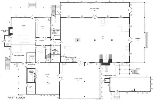
VERANDA #101
DIMENSIONS
EW 12'2' NS 48'3" ceiling 11'9"FLOOR
Painted 5 3/4" x 7/8" random length hardwood EW direction except NE corner where 45 degree joint turns boards NS until they intersect wallCEILING
Painted 3" 'V' groove boards across length of porch then turned 45 degrees in NE cornerWALLS
W wall wood shingles (exterior siding) except northern most portion that is wall of glass enclosed porchOther "walls" 5 1/2" square post (1 each corner and 3 Intermediate across length) with 1 3/4" x 9 5/8" boards 20" from floor running between posts except at open step portion
LIGHTING
Ceiling mounted incandescent fixture
ENCLOSED PORCH #102
DIMENSIONS
EW 55'0" NS 11'6" ceiling 11'9"FLOOR
3 1/4" wide hardwood boards running in NS direction with slope down, in N directionCEILING
Painted 3"—3 1/2" wide 'V' groove boards running EW directionWALLS
S wall (exterior N wall lodge building) painted, machine sawn shinglesN wall is glass (see Illustration page — for configuration); 3 middle window bays have single paned sliding windows in lower portion; all other windows single paned and fixed;
W wall was mirror image of E minus the doors; when the sprinkling system was installed in 1975, the W wall was modified to receive fire door by removing the three southern most windows; the door is in the center of this opening surrounded by a wood framed shingle wall
MOLDINGS
Base — N, S, E walls type A; W wall type B
Ceiling — type ALIGHTING
Ceiling mounted incandescent fixturesFEATURES
The porch was enclosed after the lodge had been in operation for several years. This carefully executed modification gave guests a sitting space with a most pleasing view of the Lake protected from the area's often brisk winds.
LOBBY #103
DIMENSIONS
EW 54'9" NS 35'0" ceiling 13'10" (largest room in building)FLOOR
1/4" fir running EW directionCEILING
Board and Batt — 1" x 12" boards with 1/4" x 1 5/8" batts running EW directionWALLS
2" x 6" frame construction with 1" x 12" boards and 1/4" x 1 5/8" vertical battsMOLDINGS
Base — type C
Ceiling - batt material
Plate rail — 7" wide; 9'4" from floor is found throughout except at fireplace (photograph p. )FEATURES
Two cloth tapestries in 3/4" x 3 1/2" wood frames are found on the W wall between the door to the lounge and N wall (12'11 1/2" x 6'10 1/2"; 1'11 3/4" from floor) and in the stairwell to the second floor on the S wall (9'6 1/2" x 4'8"; 7'8" from floor). Tapestries appear to be original to building.A stone fireplace 10'0" wide with 5'0" opening is found on E wall. It has a tile and concrete hearth at floor level, mantle and two tier chimney that is exposed the full height of the room. One of four counters in the space appears to be historic. It is located near the E entry to the building and is detailed compatibly with other original building elements. The other counters are of a 1950s vintage, probably installed after the facility was purchased by the Park Service.
A telephone booth circa 1950s is found on the E wall.
HEATING
A propane heater hangs in the SE corner. Its dimensions are 2'0" wide, 2'6" deep and 2'9" high and is 7'5" from the floorLIGHTING
Lighting is supplied by 7 18" diameter half globe pendant fixtures (globe down) on 3 chains each; an eighth fixture has been replaced by a flourescent fixture in the SW corner, smaller multi-faceted, (resembling leaded glass) bracket-type sources are located around the room 6'0" from floor height; wiring to these fixtures is original complete with rotating type control switchesCOMMENTS
A few minor alterations have occurred in the lobby over the years — nothing that is irreversible or of major significance. A general settling of the foundation has cause noticeable sag in the floors and racking of some of the doors and windows. Some exposed wire mold has been added to the space over the years as well as an exposed fire sprinkling system.According to historic photographs (Fig. 21) much of the original craftsmans style furnishings used in the lodge in its early days are still found on site.
STAIRS #104
Lower flight 4'1 1/4" wide (wall to edge of tread) x 7'6 3/8" long (run) x 6'4 3/8" high (rise); landing 4'7 1/2" EW x 3'6 1/2" NS; upper flight 4'3" wide x 10'3" long (run) x 8'0 5/8" high (rise); all with rubber treads
Baluster 1 3/8" square posts one per step topped with simply detailed handrail
8" square newel post with minimum detail at ground level, finial missing; plain 9 1/2" corner post extends to ceiling at landing
STORAGE #105
DIMENSIONS
EW 9'4" NS 3'3 1/2" level ceiling under landing then sloping under first stair flight to 1'6"FLOOR
Same as lobbyCEILING
Plaster on plywoodWALLS
1/2" GYP, paintedLIGHTING
Single porcelain holder, bare bulb, pull cord on wall
DINING ROOM #106
DIMENSIONS
NS 31'8" EW 39'4" ceiling 8'8"FLOOR
9" x 9" asphalt tile; off-white colorCEILING
2' x 4' accoustical tile in 'T' bar grid running NSWALLS
Vertical 4' x 8' blond wood panellingMOLDINGS
Base - type C
Ceiling — 3/4" x 6" boards positioned so 4 1/2" projects below accoustical ceilingFEATURES
The east window wall provides a pleasing view of the lodge grounds.HEATING
2 propane wall heaters located on N and S walls 1'9" x 6" (projecting into room) 5'0" high with flues running up surface of wall and penetrating ceilingLIGHTING
2' x 4' flourescent flush mountedCOMMENTS
Windows in the E and S walls originally had multi-paned transom windows (see photo page). These windows were covered when the drop ceiling was installed.
SPRINKLER ENTRY CLOSET #107
DIMENSIONS
NS 3'0" EW 4'0" ceiling 7'9" sloping in E directionFLOOR
Unpainted plywoodCEILING
Exposed 2"x4"s under roofing materialWALLS
N and S exposed batt insulation; W door; E exterior shingles of buildingLIGHTING
Single porcelain holder, bare bulb, pull chainCOMMENTS
This room is the entrance point for the main 4" fire sprinkler service pipe.
STORAGE #108
DIMENSIONS
EW 6'10" NS 8'7" ceiling 7'11"FLOOR
Unpainted plywoodCEILING/WALLS
Unpainted plywood
E and S floor to ceiling shelvesMOLDINGS
Base — type D
Ceiling and corner — type ALIGHTING
Single porcelain holder, bare bulb, pull chainCOMMENTS
This room contains the main electrical service panels and is also used for kitchen storage.
WALK-IN COOLER #109
DIMENSIONS
EW 5'9" NS 10'5" ceiling 6'8"FLOOR
Painted concreteCEILING
Painted plywood with 1/4" x 1 5/8" batts over butt jointsWALLS
Painted plywood (no treatment at butt joint)MOLDINGS
Base/ceiling/corner — type ALIGHTING
Single porcelain holder, bare bulb switched on outside near doorCOMMENTS
Floor to ceiling wood shelves are found on the E, W and N walls. The refrigeration unit is located near the ceiling on the south wall. Piping and wiring to refrigeration unit is exposed.
KITCHEN # 110
DIMENSIONS
EW 18'11" NS 24'4" ceiling S portion 7'9", N portion 9'4"FLOOR
Painted concreteCEILING/WALLS
Painted plywood (no. treatment at butt joints)MOLDINGS
Base — type E
Corner and ceiling — type ALIGHTING
Suspended flourescent fixturesCOMMENTS
The concrete floor has settled and is cracking places. Exposed sprinkler pipes, both flex and conduit wiring is found throughout. The amount kitchen equipment in place provides little room work or circulation.
SERVICE ENTRANCE #111
DIMENSIONS
EW 6'8" NS 3'11" ceiling 9'4"FLOOR
Painted concreteCEILING/WALLS
Painted plywood (no treatment at butt joints)MOLDINGS
Base — type E
Ceiling and corner — type A
EMPLOYEE'S LOUNGE #112
DIMENSIONS
'L' shape — EW 11'11" NS 13'7" with 5'10" x 7'5" projection ceiling 7'9"FLOOR
Painted concreteCEILING/WALLS
Painted plywood (no treatment at butt joints)MOLDINGS
Base — types F and G
Ceiling and corner — type AHEATING
Cylindrical propane heater W wallLIGHTING
Two single porcelain holders, base bulb, pull chainsCOMMENTS
The concrete floor is badly deteriorated. Pipes, conduit and flex wiring is exposed on walls and ceilings. A large reach-in refrigerator unit is located in the SE corner and partially blocks the door there.
STORAGE #113
DIMENSIONS
EW 7'1" NS 7'7" ceiling 7'9"FLOOR
Painted concreteCEILING/WALLS
Painted plywood (no special treatment at butt joints)MOLDINGS
Base — none
Ceiling and corner — type ALIGHTING
Single porcelain holder, bare bulbCOMMENTS
North and west walls have floor to ceiling wood shelves.
CORRIDOR #114
DIMENSIONS
EW 7'5" NS 13'8" ceiling 7'9"FLOOR
Painted concreteCEILING/WALLS
Painted plywood (no special treatment at butt joints)MOLDINGS
Base — type G
Ceiling and corner — type ALIGHTING
Incandescent pendant single bulbCOMMENTS
Exposed wiring is found throughout. The S door has been removed because of placement of ice maker.
STAIRS #115
DIMENSIONS
EW 3'10" NS 10'3" ceiling rises to second floorFLOOR
Tread and risers painted wood (see floor plan for configuration)CEILING/WALLS
Painted plywood (no special treatment at butt joints)MOLDINGS
Base — type E, N wall
Ceiling and corner - type A
Handrails — 1 1/2" diameter 2" from wall 2'7" from floorLIGHTING
NoneCOMMENTS
Exposed pipe and wires are found throughout.
LIQUOR STORAGE #116
DIMENSIONS
2 spaces North — EW 3'10" NS 2'8" ceiling 7'9" South — EW 3'10" NS 7'2" ceiling exposed to stair structureFLOOR
North — painted concrete
South — 3 3/8" wood boards EW directionCEILING
North — painted plywood
South — unpainted plywood, exposed ceilingMOLDINGS
North — ceiling type A on E side onlyLIGHTING
Single porcelain holder, bare bulb, pull chain each spaceCOMMENTS
The N room has floor to ceiling wood shelves on the E wall measuring 1'7" deep. S room has floor to ceiling wood shelves 9" deep on E and W walls.
RESTROOMS, MENS/WOMENS #117 AND 119
DIMENSIONS
Men — EW 6'7" NS 6'10" ceiling 7'10"
Women — EW 6'7" NS 7'4" ceiling 7'10"FLOOR
12" x 12" vinyl tileCEILING/WALLS
Painted plywood (no treatment at butt joints)MOLDINGS
Base — type F
Ceiling and corner — type ALIGHTING
Single porcelain holder, bare bulbCOMMENTS
Rooms are subdivided into two compartments with plywood and wood frame screens that begin 6" above the floor and stops 6" below the ceiling.
CORRIDOR #118 & #120
DIMENSIONS
EW 11'8" NS 5'7" ceiling 7'9"FLOOR
Painted concrete with rubber runner overCEILING/WALLS
Painted plywood (no treatment at butt joint)MOLDINGS
Base — type G, NE corner; all other type H
Ceiling and corner — type ALIGHTING
Incandescent pendant single bulb
OFFICE #121
DIMENSIONS
EW 11'8" NS 15'5" ceiling 7'9"FLOOR
Carpet over concreteCEILING/WALLS
Stained plywood (no treatment at butt joint)MOLDINGS
Base — type G
Ceiling and corner — type AHEATING
Propane heater NE corner resting on floor, 1'11" wide, 10'0" deep and 2'1" high flue rises vertically 3'0" and turns horizontally to eachLIGHTING
2-4'0" flourescent fixtures surface mounted on ceilingCOMMENTS
Exposed pipes and wires are found throughout.
LOUNGE #122
DIMENSIONS
EW 19'4" NS 21'4" ceiling 7'9"FLOOR
Painted concreteCEILING
4' x 8' sheets knotty pine; 1/4" x 1 9/16" batts EW directionWALLS
4' x 8' sheets knotty pine; 1/4" x 1 9/16" batts vertical directionMOLDINGS
Base — type G
Ceiling and corner — batt materialFEATURES
Centered on the W wall is a "common" brick fireplace with a flush face, no hearth and 1" x 4" mantle 4'11" from the floor.
South wall has a bar and back bar, EW 8'2" by NS 7'2 1/2" with a mirror on the wall above the back bar.LIGHTING
Wall mounted pendant type, with one or two fixtures per bracket. All fixtures are controlled by a pull chain on each.COMMENTS
Pipes and wiring are exposed throughout.
WATER HEATER ROOM #123
DIMENSIONS
EW 4'6" NS 8'4" ceiling 8'2"FLOOR
2" x 10" boards NS direction with 1/8" crack betweenCEILING/WALLS
1/4" grey asbestos panelsCOMMENTS
This room contains three propane water heaters.
|
|
FIRST FLOOR (click on image for a PDF version) |
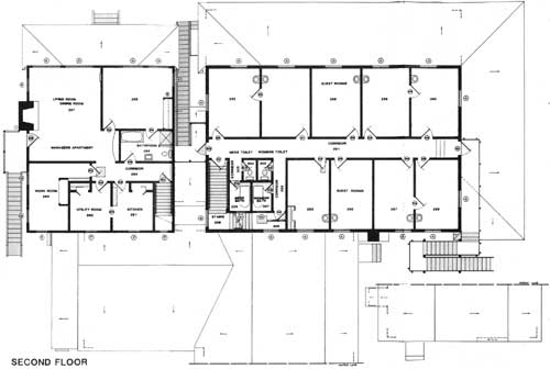
CORRIDOR #201
DIMENSIONS
EW 54'11" NS 4'1" ceiling 8'8"FLOOR
Carpet over plywood (historic hardwood floor was removed when plywood installed)CEILING
1' x 12" boards with 1/4" x 1 5/8" batts EW directionWALLS
1' x 12" boards with 1/4" x 1 5/8" vertical battsMOLDINGS
Base — type I
Ceiling and corner — batt materialLIGHTING
2 pendant globes with individual pull chainsCOMMENTS
This room has three risers at the E end leading to an emergency stairway constructed in 1975. The landing at the door is 2'11" long. The risers are wood and are 6 3/4" to 7 1/4" high and rise a total of 1'9".
Sprinkler pipes are exposed throughout.
CORRIDOR #202
DIMENSIONS
EW 2'8 1/2" NS 11'6" ceiling 8'8"FLOOR
Carpet over 3 5/16" wide hardwood EW directionCEILING
1" x 12" boards with 1/4" x 1 5/8" batts EW directionWALLS
1" x 12" boards with 1/4" x 1 5/8" vertical battsMOLDINGS
Base — type I
Ceiling and corner — batt materialLIGHTING
NoneCOMMENTS
Sprinkler pipes exposed throughout.
WOMENS TOILET #203, MENS TOILET # 204
DIMENSIONS
Womens — EW 3'1" NS 4'6" ceiling 8'1"
Mens — EW 2'11" NS 4'6" ceiling 8'1"FLOOR
12" x 12" vinyl tile over wood floor raised 6 1/2" at door (raised edge is flush with corridor)CEILING
Painted plywoodWALLS
3 1/4" vertical 'V' groove board all walls except E wall womens, W wall mens that are masonite; all are paintedMOLDINGS
Base/ceiling/corner — type A
Base (mens) — type FHEATING
2'0" electric baseboard each room, womens W wall N end; mens E wall N endLIGHTING
Incandescent metal lamp holder, single bulbCOMMENT
Each room contains one water closet against the S wall centered (EW) in room.
CORRIDOR #205
DIMENSIONS
EW 2'8" NS 4'11" ceiling 8'8"FLOOR
Rubber runner over 3 5/16" wide hardwood EW directionCEILING
1" x 12" boards with 1/4" x 1 5/8" batts EW directionWALLS
1" x 12" boards with 1/4" x 1 5/8" vertical battsMOLDINGS
Base — type I
Ceiling and corner — batt materialLIGHTING
None
MENS BATH #206, WOMENS BATH #207
DIMENSIONS
Mens — EW 4'9" NS 6'4" ceiling 8'1"
Womens — EW 4'4" NS 6'4"FLOOR
12" x 12" vinyl tile over floor raised 6 1/2" edge is flush at corridorCEILING
Painted plywoodWALLS
3 1/4" vertical 'V' groove board except S walls that are masonite; all paintedMOLDINGS
Base — all type A
Ceiling and corner — type AHEATING
2'0" electric baseboard each room, mens S wall W end, womens E wall S endLIGHTING
Residential type glass box with 4 incandescent bulbs insideCOMMENTS
Both bathrooms have 5'6 1/2" long. 2'6" wide, 1'10 1/2 high claw foot bathtubs against the common wall.
CORRIDOR #208
DIMENSIONS
EW 7'5" NS 3'6" ceiling 8'8"FLOOR
3 5/16" wide hardwood EW direction with access panel 2'1" x 1'7" in middle of spaceCEILING
1" x 12" boards with 1/4" x 1 5/8" batts EW directionWALLS
1" x 12" boards with 1/4" x 1 5/8" vertical battsMOLDINGS
Base — type I
Ceiling and corner — batt materialLIGHTING
NoneCOMMENTS
SE corner of room has vertical riser for attic sprinkling system.
STAIRS #209
DIMENSIONS
Lower flight — 3'8" wide (wall to wall) 5'0" long (run) 4'8" high (rise) 7 treads at 8 1/2' (+3/4" nosing) 8 risers at 7"
Landing — EW 4'6" NS 3'9"
Upper flight — 4'2" wide (wall to wall) 5'0" long (run) 4'8" high (rise) 7 treads at 8 1/2" (+3/4 nosing) 8 risers at 7"CEILING
Open to atticWALLS
Board and batten (same as second floor corridors)MOLDINGS
None
No handrailsLIGHTING
NoneCOMMENTS
This stairway leads to the third floor attic and is closed to the public.
GUEST ROOMS #252 THROUGH 260
DIMENSIONS
Room widths (EW) vary from 8'8" (#257) to 11'2" (#252); length (NS) is 14'10" N rooms, 15'1" S rooms; ceiling heights 8'8"FLOOR
3 5/16" wide hardwood EW directionCEILING
1" x 12" boards with 1/4" x 1 5/8" batts EW directionWALLS
1" x 12" boards with 1/4" x 1 5/8" vertical battsMOLDINGS
Base — type I
Ceiling and corner — batt materialFEATURES
All rooms have one window (type ), except corner rooms (#252, 259, 269) that have one on each side wall.
Some rooms are connected to neighboring rooms via a common pass door.
Each room has a lavatory. 1'7 1/2" wide by 1'4 1/2" deep projecting from wall.HEATING
6'0" electric baseboard heaters under windowsLIGHTING
Incandescent ceiling pendants with pull chainsCOMMENTS
Room #253 has a 4' x 10' cut plywood ceiling running in EW direction and a 1'1" EW by 3'2" NS plywood panel in the floor at the door. The flooring in this room was removed and reinstalled to correct water damage. A 5'0" by 1'8" deep closet was added in the SW corner.
MANAGER'S APARTMENT KITCHEN #261
DIMENSIONS
EW 8'10" NS 10'3" ceiling 8'0"FLOOR
12" x 12" decorative vinyl tileCEILING
Painted plywood, NS direction (no batts at butt joints)WALLS
Painted plywood, vertical direction (no batts at butt joints)MOLDINGS
Base - type J
Ceiling and corner - type ALIGHTING
Single flourescent fixtureCOMMENTS
The west wall has a 2'5" cased opening connecting with the utility room. A 2'0" by 5'2" closet is found in the NE corner.
MANAGER'S APARTMENT UTILITY ROOM #262
Same as kitchen (#261) except 2'0" by 4'9 1/4" closet located in NW corner and lighting in ceiling is a single incandescent bulb in a porcelain holder.
MANAGER'S APARTMENT WORKROOM #263
DIMENSIONS
EW 8'8" NS 14'7" ceiling 8'0"FLOOR
LinoleumCEILING
Painted plywood, NS direction (no batts at butt joints)WALLS
Painted plywood, vertical direction (no batts at butt joints)MOLDINGS
Base — type J
Ceiling and corner — type ALIGHTING
Ceiling mounted flourescent and incandescent fixture
MANAGER'S APARTMENT CORRIDOR #264
DIMENSIONS
EW 17'7" NS 3'11" ceiling 8'0FLOOR
Carpet over plywoodCEILING
Painted plywood, EW direction (no batts at butt joints)WALLS
Painted plywood, vertical direction (no batts at butt joints)MOLDINGS
Base — type J
Ceiling and corner — type ALIGHTING
Ceiling mounted incandescent lamp holderCOMMENTS
An access panel to the attic is located in the W end of the corridor. The panel is 1'0" off the W and S walls. Its dimensions are 1'10 3/4" EW by 2'1" NS.
MANAGER'S APARTMENT BATH #265
DIMENSIONS
EW 11'3" NS 6'8" ceiling 8'0"FLOOR
Carpet over plywoodCEILING
Painted plywood, NS direction (no batts at butt joints)WALLS
Painted plywood, vertical direction (no batts at butt joints)MOLDINGS
Base — type J
W Ceiling and corner type AHEATING
Electric baseboardLIGHTING
Ceiling mounted incandescent lamp holderCOMMENTS
A divider between the shower stall and toilet, built with 2'x6's and plywood projects from the E wall.
MANAGER'S APARTMENT BEDROOM #266
DIMENSIONS
EW 15'4" NS 13'4" ceiling 8'0"FLOOR
CarpetCEILING
Painted plywood, NS direction (no batts at butt joints)WALLS
Painted plywood, vertical direction (no batts at butt joints)MOLDINGS
Base — type J (without quarter round)
Ceiling and corner — type AHEATING
8" cylindrical propane heater centered on E wallLIGHTING
Ceiling mounted incandescent lamp holderCOMMENTS
A 2'0" x 6'10 3/4" free standing closet is located in the SE corner.
MANAGER'S APARTMENT LIVING/DINING ROOM #267
DIMENSIONS
EW 15'8" NS 20'4" extension SE corner EW 4'0" by NS 6'3 1/2" ceiling 8'0"FLOOR
Carpet over plywoodCEILING
Painted plywood with 1/4" x 1 1/2" batts NS directionWALLS
Painted plywood with 1/4" x 1 1/2" batts vertical directionMOLDINGS
Base — type J (without quarter round)
Ceiling and corner — batt materialHEATING
1'9" wide by 5'0" high propane heater partially recessed (2" exposed) in E wall, N endLIGHTING
Ceiling mounted incandescent lamp holder
|
|
SECOND FLOOR (click on image for a PDF version) |
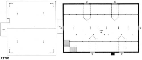
ATTIC #301
DIMENSIONS
EW 54'9" NS 35'0" ceiling to raftersFLOOR
3 5/8" x 1/4" soft wood running in EW directionCEILING
Open to raftersWALLS
Open to framingLIGHTING
Ceiling mounted incandescent fixturesCOMMENTS
Addition columns have been added to reduce the rafter span of the roof framing. Windows are racked due to foundation settlement.
|
|
ATTIC (click on image for a PDF version) |
Elevations
|
|
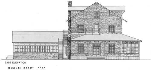
EAST ELEVATION (click on image for a PDF version) |
|
|
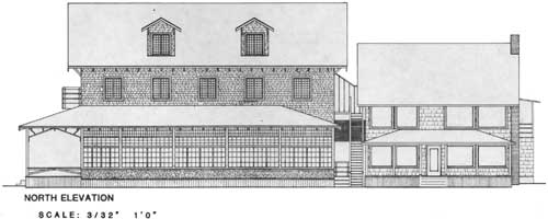
NORTH ELEVATION (click on image for a PDF version) |
|
|
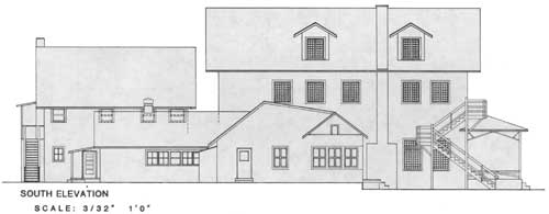
SOUTH ELEVATION (click on image for a PDF version) |
|
|
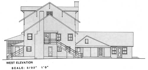
WEST ELEVATION (click on image for a PDF version) |
Doors
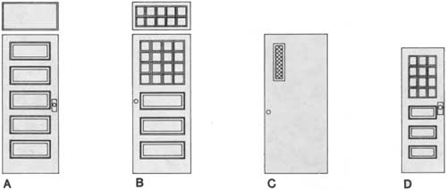
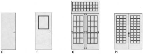
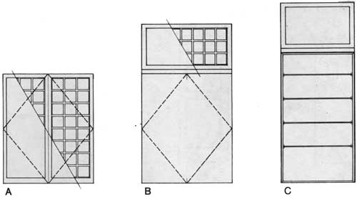
Feature Door Schedule
| Door No. | Type | Size | Description | Lite Size | Trim Type |
Remarks |
| 101 | G | 2-2'6"x6'6"x1 3/4" | Wood | Clear Glass 6 1/8"x11 1/8" | ||
| 102 | G | 2-2'6"x6'5"±x1 3/4" | Wood | Clear Glass 6 1/8"x11 1/8" | No Transom Floor Slopes | |
| 103 | G | 2-2'6"x6'6"x1 3/4" | Wood | Clear Glass 6 1/8"x11 1/8" | No Pane Hardware | |
| 104 | E | 3'0"x6'8"x1 3/4" | Wood S.C. | |||
| 105 | P | 2'8"x6'8"x1 3/8" | Wood Panel | Textured Glass | w/Transom | |
| 106 | R | 2'9"x5'8"x3/4" | 3/4" Plywood | |||
| 107 | H | 2-2'6"x6'6"x1 3/8" | Wood | Clear Glass 6 3/8"x5 1/8" | ||
| 108 | L | 3'0"x6'7"x1 3/8" | Wood | Clear Glass 5 7/8"x5 5/8" | ||
| 109 | F | 3'0"x6'8"x1 3/4" | Wood S.C. | Clear Glass | ||
| 110 | E | 2'8"x6'8"x1 3/4" | Wood H.C. | |||
| 111 | N | 2-3'0"x6'7"x1 3/8" | Wood S.C. | Clear Glass | Double Acting | |
| 112 | A | 2'6"x6'4"x1 3/8" | Wood Panel | No Transom | ||
| 113 | F | 2'8"x6'6"x1 3/4" | Wood S.C. | Clear Glass | ||
| 114 | A | 2'6"x6'4"x1 3/8" | Wood Panel | No Transom | ||
| 115 | *J | 2'6"x6'6"x1 3/8" | Wood Panel | |||
| 116 | *J | 2'8"x6'6"x1 3/8" | Wood Panel | |||
 | ||||||
| 117 | Q | 2'6"x6'2"x1 3/8" | Wood Panel | Clear Glass | ||
| 118 | *J | 2'8"x6'6"x1 3/8" | Wood Panel | |||
| 119 | J | 3'0"x6'8"x1 3/8" | Wood Panel | |||
| 120 | J | 2'4"x6'5"x1 3/8" | Wood Panel | |||
| 121 | J | 2'6"x6'6"x1 3/8" | Wood Panel | |||
| 122 | J | 2'6"x6'6"x1 3/8" | Wood Panel | |||
| 123 | K | 2'8"x6'8"x1 3/8" | Wood | Clear Glass S 1/6"x5 3/16" | ||
| 124 | J | 2'8"x6'6"x1 3/8" | Wood Panel | |||
| 125 | J | 2'8"x6'8"x1 3/8" | Wood Panel | |||
| 126 | J | 2'11"x6'7"x1 3/4" | Wood | Clear Glass | ||
| 127 | R | 2'1"x4'7"x1" | 1" Plywood | |||
| 128 | P | 2'8"x6'8"x1 3/8" | Wood Panel | |||
| 201 | F | 3'0"x6'8"x1 3/4" | Wood S.C. | Clear Glass 1'11 5/8"x2'5 1/2" | ||
| 202 | A | 2'8"x6'8"x1 3/8" | Wood Panel | |||
| 203 | A | 2'8"x6'8"x1 3/8" | Wood Panel | |||
| 204 | A | 2'8"x6'8"x1 3/8" | Wood Panel | No Transom | ||
 | ||||||
| 205 | A | 2'8"x6'8"x1 3/8" | Wood Panel | |||
| 206 | A | 2'8"x6'8"x1 3/8" | Wood Panel | No Transom | ||
| 207 | A | 2'8"x6'8"x1 3/8" | Wood Panel | |||
| 208 | A | 2'8"x6'8"x1 3/8" | Wood Panel | |||
| 209 | A | 2'8"x6'8"x1 3/8" | Wood Panel | |||
| 210 | A | 2'8"x6'8"x1 3/8" | Wood Panel | |||
| 211 | A | 2'8"x6'8"x1 3/8" | Wood Panel | |||
| 212 | A | 2'8"x6'8"x1 3/8" | Wood Panel | No Transom | ||
| 213 | A | 2'8"x6'8"x1 3/8" | Wood Panel | |||
| 214 | B | 2'9"x6 '8"x1 3/8" | Wood Panel | Clear Glass 5 5/8"x5 1/2" | ||
| 215 | C | 3'0"x6'8"x1 3/4" | Wood S.C. | Wire Glass 4"x1 '7" | ||
| 216 | D | 2'0"x6'0"x1 3/8" | Wood Panel | Textured Glass 4 1/2"x5 1/4" | ||
| 217 | D | 2'0"x6'0"x1 3/8" | Wood Panel | Textured Glass 4 1/2"x 5 1/4" | ||
| 218 | D | 2'0"x6'0"x1 3/8" | Wood Panel | Textured Glass 4 1/2"x5 1/4" | ||
| 219 | D | 2'0"x6'0"x1 3/8" | Wood Panel | Textured Glass 4 1/2"x5 1/4" | ||
| 220 | E | 2'7"x6 '8"x1 3/4" | Wood S.C. | |||
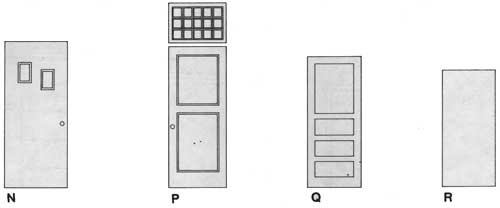 | ||||||
| 221 | P | 2'8"x6'5"x1 3/8" | Wood Panel | Clear Glass | ||
| 222 | J | 2'0"x6'6"x1 3/8" | Wood Panel | |||
| 223 | *P | 2'6"x6'8"x1 3/8" | Wood Panel | Textured Glass | ||
| 224 | 2'5"x6'7" | Cased Opening | ||||
| 225 | P | 2'8"x6'8"x1 3/8" | Wood Panel | Textured Glass | ||
| 226 | J | 2'0"x6'6"x1 3/8" | Wood Panel | |||
| 227 | P | 2'6"x6'8"x1 3/8" | Wood Panel | Textured Glass | ||
| 228 | *P | 2'8"x6'8"x1 3/8" | Wood Panel | Textured Glass | ||
| 229 | P | 2'6"x6'8"x1 3/8" | Wood Panel | Textured Glass | ||
| 230 | P | 2'6"x6'8"x1 3/8" | Wood Panel | Textured Glass | ||
| 231 | P | 2'6"x6'8"x1 3/8" | Wood Panel | Textured Glass | ||
| 232 | N | 3'0"x6'11"x1 3/4" | Wood S.C. | Clear Glass 5"x8 7/8" | ||
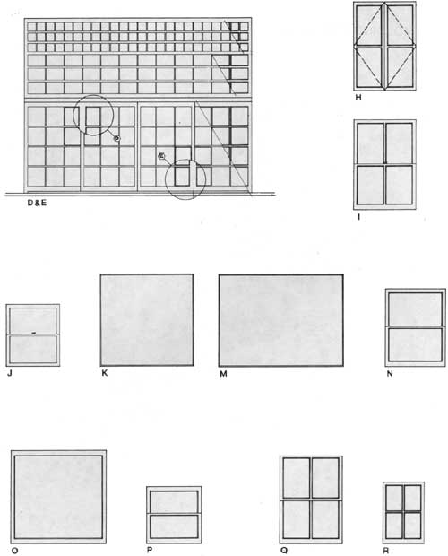
Windows
Feature Window Schedule
| Type | Size | Description | Lite Size | Trim Type |
Remarks |
| A | 3'9"x4'7" | Casement | |||
| B | 3'9 9/16"x6'7 3/4" | Casement W/Transom | Configuration Same as 'A' | ||
| C | 3'3/4"x7'6 1/2" | Glass Display Case | Transom Same as Type 'B' | ||
| D,E | 11'3 1/2"x8'8 3/4" | Type 'D' Sliders Type 'E' Fixed | 2 Center Panels Slide in Type D' | ||
| F,G | Similar to D & E | ||||
| H | 3'1 1/8"x4'6" | Casement | |||
| I | 3'1"x4'5 7/8" | Hung | |||
| J | 2'8"x3'7/8" | Hung | |||
| K | 4'7 5/8"x4'7" | Fixed (Picture) | |||
| L | |||||
| M | 6'2"x4'7" | Fixed (Picture) | |||
| N | 3'0"x3'10 1/4" | Hung | |||
| O | 4'8 5/8"x4'7 3/4" | Fixed Sash | |||
| P | 2'8 1/2"x2'10 1/8" | Hung | |||
| Q | 3'1"x4'4 5/8" | Hung | |||
| R | 2'3/4"x2'10" | Fixed Sash |
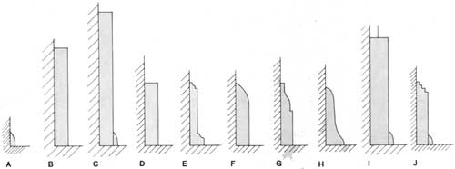
Molding Types
| <<< Previous | <<< Contents>>> | Next >>> |
lake_crescent_lodge/sec3.htm
Last Updated: 23-Jul-2010