|
CAMP STOVES AND FIREPLACES
|
|
CONSTRUCTION DETAILS
FOR the successful design and construction of camp stoves and fireplaces, it is most essential that the details of design and construction should be given the most thorough consideration. Inasmuch as these details may apply to a number of types of camp stoves or fireplaces, it has been deemed advisable to arrange these construction details for ready reference, upon the following sheets (pls. XXI, XXII, and XXII—A).
There are a number of variations in these details and it is only the purpose of these three drawings to provide detailed information concerning the fundamental information which is necessary for reference in connection with construction details for these features.
CONSTRUCTION DETAILS
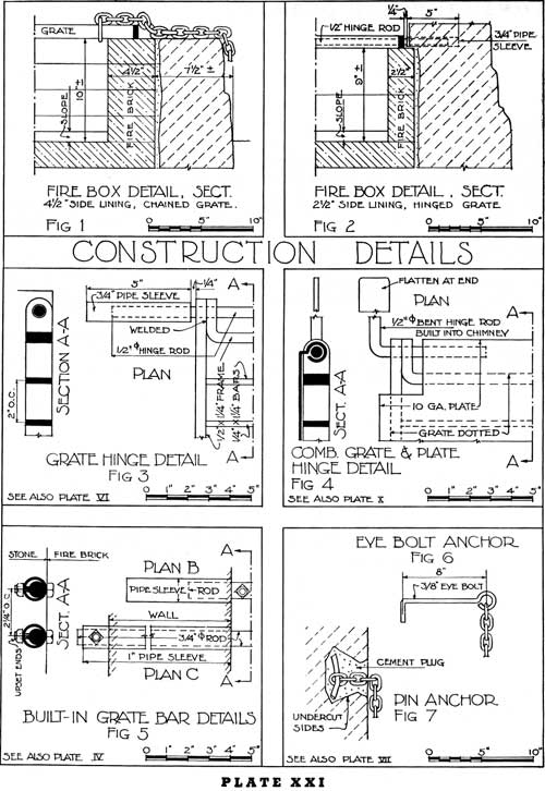
FIGURE 1
Section through firebox lined with 4-1/2 inches of fire-clay brick at sides and 2-1/2 inches of fire-clay brick on hearth. The grate is chained.
FIGURE 2
Section through firebox, with 2-1/2 inches of fire-clay brick side lining and hearth. The grate is hinged. (For hinge detail, see fig. 3.)
FIGURE 3
Grate hinge detail. The grate frame is extended at hinge side as shown—the ends being welded together. The extended portions have a 5/8-inch diameter hole for passage of hinge rod. The 1/2-inch diameter hinge rod is held in 3/4-inch pipe sleeves built into the masonry.
FIGURE 4
A further development of the grate hinge shown in figure 3. Here a solid plate is hinged on to the same hinge rod carrying the grate. The solid plate may be thrown back independently of the grate; or both plate and grate may be thrown open, converting the fireplace into a warming reflector. In this detail, the hinge bars are two separate bent sections, with flattened ends, built into the chimney (also see pl. X).
FIGURE 5
Detail of built-in grate bars. The bars are let into pipe sleeves, allowing for expansion. They may or may not be arranged in such a way that removal and replacement can be taken care of in case of damage.
In plan B, the bolts near either end of the rod are removed. The rod is slipped back into one sleeve pocket, freeing the other end for complete removal.
In plan C, one or both ends of the rod, together with its pipe sleeve fitting, pass completely through the side walls of the fireplace, with bolts as shown, for securing the rod in place.
FIGURE 6
Eye bolt chain anchor.
FIGURE 7
Pin chain anchor.
In addition to types shown, the end of the chain may be spiked to a post, or log deadman sunk into the ground.
|
|
PLATE XXI. (click on image for a PDF version) |
CONSTRUCTION DETAILS
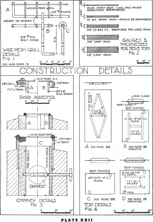
FIGURE 1
Wire-mesh grill details. A heavy woven mesh or reenforcing mesh is welded or hooked around a rod frame, and the resulting grate may either be chained to the fireplace or hinged, as shown, by means of eyebolt hinges.
FIGURE 2
There is great variance of opinion as to the respective merits of solid tops or open grates. Also as to the respective merits of cast iron and sheet iron. (See general discussion.) The various thicknesses are indicated.
FIGURE 3
A chimney is shown lined on the one hand with fire-clay brick, and, as a variation, with terra cotta flue lining.
"A", "B", and "C" show various types of spark arresters.
A damper is shown below.
FIGURE 4
Various designs of angle iron reenforcing are welded to the underside of the plates. Additional dispositions of the angles are possible in a number of ways. In the case of cast-iron tops, the reenforcing ribs are an integral part of the casting and by some persons the cast-iron top with such reenforcing is preferred.
Holes are conveniently spotted in the tops to facilitate easier handling.
Bent flanges may decrease the danger of sagging.
|
|
PLATE XXII. (click on image for a PDF version) |
CONSTRUCTION DETAILS
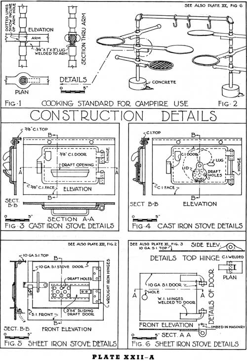
COOKING STANDARD FOR CAMPFIRE USE
This cooking standard may be used either as a single standard (pl. XX, figs. 5 and 6) or as a double standard (pl. XXII—A, figs. 1 and 2). It is a simple unit of use primarily on picnic areas, and especially adapted for use by hunters and fishermen.
In this unit, facilities are provided for broiling on a grate, and for cooking otherwise on a plate or grate. Kettles may be hung on the hooks shown in figure 2.
This unit is generally installed with a small campfire circle. The provision for raising or lowering the irons on which the cooking is done, is shown in the details under figure 1.
The idea of the double standard shown in figure 2 originated in region 1 of the Forest Service.
CAST IRON AND SHEET IRON, STOVE DETAILS
The important requirements to be fulfilled in the design for the door on the front of the firebox are as follows:
(a) To construct the door of a quality of iron which will prevent the door from warping when exposed to heat.
(b) To make provisions so that the door may be securely closed.
(c) To provide a draft opening in the door.
(d) To provide hinges so that the door will remain hanging in its correct position.
The draft in the door as shown in figures 3, 4, and 5 may be through an opening which is constant (as in fig. 3), or it may be through holes, the area of which may be increased or decreased by a revolving lid (as in fig. 4), or by a sliding damper (as in fig. 5). If the type of draft opening shown in figure 3 is used, it seems advisable to install, in addition, a damper in the chimney to properly control the draft. The damper in the chimney is not generally required when there is provision for opening and closing the front draft as shown in figures 4 and 5.
Four methods of hinging the door at the front of the firebox are shown in figures 3, 4, 5, and 6. The method of attaching the doors with hinges as shown in figure 5 is the least desirable, and the methods shown in figures 3 and 4 are the most desirable. The kind of hinge shown in figure 5 does not always hold the door solidly in place.
Doors are also hinged at the top and at the bottom. The hinging of doors at the bottom should be discouraged, and the hinging of doors at the top does not seem to be as practical in actual use as hinging the doors on the side.
|
|
PLATE XXII-A. (click on image for a PDF version) |
FIREPLACE CONSTRUCTION
WITHIN SHELTERS
THE design of the fireplace to be constructed within a shelter must follow closely the fundamental requirements for the design of any interior fireplace. Ordinarily, the fireplace designed within a shelter building and primarily for use for warming purposes is higher and wider than the normal fireplace in the average residence.
The following are some of the important requirements which should be recognized in developing a proper design for such a fireplace.
GENERAL DESIGN
Any well-designed fireplace should have a proper draft which will eliminate any smoking.
The back of the fireplace should slope forward to the rear line of the throat as shown in the drawing. The maximum heat can be radiated into the room by splaying the sides.
The lining of the fireplace should be of fire-clay brick, carefully laid in accordance with the directions contained on page 14.
THROAT AND FLUE
The most important detail of fireplace design concerns the throat and the flue, either or both of which, if not properly designed, cause failure in the practical use of the fireplace.
The horizontal net sectional area of the flue should be about one-twelfth to one-tenth of the area of the fireplace opening. The normal fireplace opening ranges from 2 feet 6 inches to 4 feet in width, 16 to 22 inches in depth, and 2 feet 6 inches to 3 feet in height. If the fireplace is abnormally high, then the area of the flue should be increased and may be as much as one-eighth of the area of the fireplace opening, in order to provide an adequate draft to properly remove the smoke.
In computing the area for the flue, care should be exercised to make certain that the net area is adopted. The sizes of the tile used for lining the flue are apt to be misleading in that round tile are designated by inside measurements and the rectangular or square tile are designated by outside measurements.
In the higher fireplaces with normal area of flue, all of the fire should be back of the rear line of the hood at the top of the fireplace. In reality, the damper in the fireplace constructed in shelter buildings can well be eliminated if the throat and flue are properly designed.
The throat should extend across the full width of the opening at the top of the fireplace and the front line of the throat should be as near the front of the fireplace as it is practical to make it. Its sectional area should be (when the damper is open) the same or very little less than that of the flue.
The flue must be reduced to its normal required size by sloping the sides as shown in the elevation, and the center of the flue must be directly over the middle of the fireplace. Any deflection which is to occur in the alinement of the flue must occur above this point where the flue reaches a normal and constant area. If the flue is deflected to one side immediately as it leaves the throat, one side of the fireplace will smoke.
The interior of the flue should not be plastered, as is sometimes done. This is not good construction because the plaster is apt to peel and break away from the brickwork, thus clogging the flue.
The down current of cold air which may occur when the fire is being started is overcome by the construction of a flat shelf. This shelf deflects the down-current of cool air and carries it back into the up-current of warm air. If this shelf is not constructed, there is a down draft at the back of the fireplace, especially when the fire is being started, thus driving smoke into the room. This down draft does not occur after the fire is well started and the flue is sufficiently heated so that the entire air current is upward. The smoke shelf might be sloped slightly, in order that if any rain comes down the chimney during heavy storms this moisture would drain into the fireplace.
In many fireplaces, a damper is desirable. This damper should be installed as shown in the detail and must open through the full length of the throat. The damper in the throat of the fireplace is really only necessary in order to close the fireplace during the period of the year when the fireplace is not in use, and thus protect the interior of the building against any drafts of cool air, insects, etc., which might come through the chimney.
The flue is usually lined with terra cotta in preference to any other construction.

|
|
PLATE XXIII. (click on image for a PDF version) |
| <<< Previous | <<< Contents>>> | Next >>> |
|
camp-stoves-fireplaces/sec7.htm Last Updated: 12-Sep-2011 |