|
CAMP STOVES AND FIREPLACES
|
|
DETAILED DISCUSSION OF SPECIFIC TYPES
ADAPTATION TO LOCATION AND USE
DESIGN AND CONSTRUCTION
VARIATIONS IN DESIGN
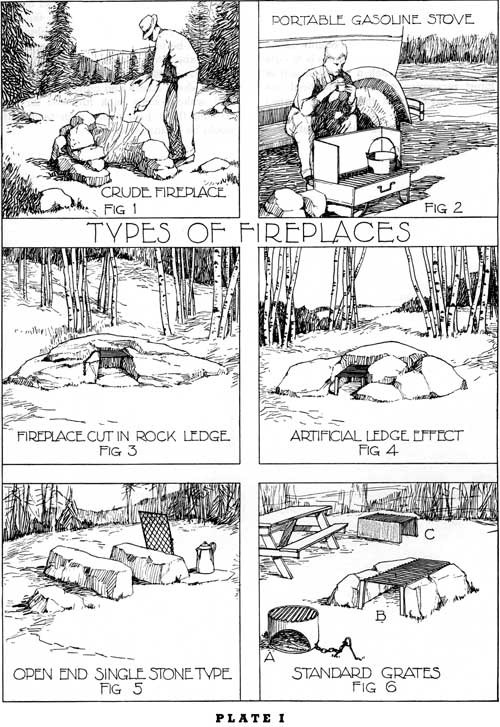
ON THE following plates are shown different types of camp stoves and fireplaces, ranging from the very elementary and primitive type (pl. I, fig. 1), to the very "sophisticated" and artificial type (pl. I, fig. 2). In connection with each specific type of camp stove and fireplace, there is presented a discussion of the problems of adaptation to location and use, and of the problems of design and construction.
In the minds of some readers, these drawings may indicate in some instances solutions which seem rather ideal, and not capable of practical application because of the fact that the most desirable kinds and shapes of stones necessary to produce the effect shown in the drawings are not available. These drawings are intended to show only in a general way the kind of design which may be followed in actual construction. Minor modifications are often necessary on account of varying materials and conditions on different areas in different parts of the country.
The success or failure in procuring the kind of results illustrated in the drawings depends upon the ability of the man who is superintending the construction work in the field, and of the stone mason who is doing the work of actual construction.
THE simple types shown in figures 1, 3, 4, 5, and 6B, are appropriate for forest picnic areas. They are not adapted for campgrounds except where the camper desires to accept the natural inconvenience accompanying "life in the wild." Their simplicity, crudeness of construction, and inconspicuous mass are strongly in their favor.
FIGURE 1
Crude Fireplace of Boulders or Rocks Loosely Piled in the Shape of a Horseshoe.—This type is not conspicuous; it is inconvenient in use and creates an abnormal fire hazard. It has a place on large open picnic areas because it is not conspicuous. If this is the only type of fireplace provided on the campgrounds, the majority of the campers and picnickers will use some kind of a portable gas stove (pl. I, fig. 2) for cooking purposes. The construction of this type of fireplace will vary, depending on the available stone (whether of the boulder type or of the stratified type). In portions of the country where a stratified stone is available, a few flat stones might be used on which to set pots and pans for warming purposes.
This fireplace is adapted for use as a campfire for light, and especially for warmth in the cool evening hours. In the eastern part of the country, where such a large percentage (in some instances more than 80 percent) of the campers use portable stoves, it is a most practical feature to supplement the gasoline stove.
FIGURE 2
Portable Gasoline Stove.—This stove is frequently used by campers and picnickers especially where there is a scarcity of fuel and lack of properly designed camp stoves and fireplaces adapted for convenient use. It has limited cooking surface, provides quick heat for cooking, and it is also of practical value in rainy weather.
FIGURE 3
Fireplace Cut in Rock Ledge.—This type of fireplace is very attractive, but often destructive of the natural beauty of the rock out-crop. Such a fireplace is often expensive to construct. It cannot be conveniently used from the sides, and therefore must be of minimum length (15 to 18 inches). A grate of desired length similar to the grate shown in figure 4 may be used. The grate on such a fireplace must be movable, and attached to the ledge with a chain. In ledge rock which will not withstand extremely high temperatures, it is desirable to construct a fire-clay brick lining in order to protect the stone in the natural ledge.
FIGURE 4
Artificial Ledge Effect.—The proposed grate may be either a standard grate such as shown in figure 6B, or a movable grate chained to the rock. In localities where a suitable type of ledge rock is available, the construction of this type of fireplace may not involve an abnormal expense, and may be a most interesting feature.
FIGURE 5
Open End Single Stone Type.—This is the simplest form of open fireplace, and is to be strongly discouraged where fire hazard is present. If the stones are carefully selected, this fireplace is desirable for use on open picnic areas.
FIGURE 6
Standard Grates.—This figure shows three kinds of standard grates often used for picnic purposes. Each is simple in design, and not unduly conspicuous.
Type "C" is a simple grate with sheet iron sides. Type "B" is the same kind of a grate with large rocks at each side. The grate in each of these fireplaces is supported by four legs, each of which may be solidly anchored as shown on plate III, figures 4 and 5. Type "B" is the more appropriate type. The grate marked "A" is not desirable except on intensively used picnic areas where the occupancy varies from that of maximum use to that of little use on successive days or week-ends. There is to date little reason for using such a portable unit in the forest recreation areas. In practical use the fire is started, and the grate is placed over it.
Simple fireplaces of the types similar to figures 5 and 6B should be adopted generally for use in designated locations on the "Primitive areas", where some crude fireplace facilities must be provided; but limited to only such as are absolutely necessary for fire protection. There are certain strategic places even in these areas where hikers and canoeists must camp, and without some such facilities for simple cooking these practically unprotected areas would be in danger of fire.
|
|
PLATE I. (click on image for a PDF version) |
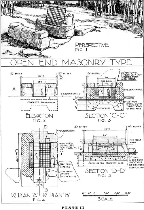
OPEN END MASONRY FIREPLACE
ADAPTATION TO LOCATION AND USE
The open ends may provide a better draft in locations where the prevailing winds are in opposite directions in the morning and in the evening, and may further vary during the day. This type is ordinarily used with a grate. A solid plate, attached to the stonework by a chain could, when not used as a cooking top, be set up against one end of the fireplace to control the draft. It is excellently adapted for use on large open picnic areas because it is low and not conspicuous. The disadvantage of this type is that a strong current of air will scatter the sparks and create a definite fire hazard.
DESIGN AND CONSTRUCTION
The stonework on the sides should be informal and rustic so far as the available material will allow, and should conceal the fire-clay brick lining and soften the general appearance.
A "floating pad foundation", reinforced as shown in the drawings, consisting of a concrete slab, the top of which is placed slightly below ground level, is required. This type of foundation will heave and settle under frost action without damaging the stone masonry superstructure. It is not essential in this type of fireplace to carry the foundation walls below the frost line.
The hearth of the firebox is slightly (1 to 2 inches) above the ground level and may be constructed of porous soil, mineral earth, or fire-clay brick. The hearth should be raised in the middle and pitched towards either end in order to provide proper drainage.
The open-ended firebox (approximating 10 inches in height) will accommodate longer lengths of wood than the three sided type (pl. III). This firebox should be lined with fire-clay brick and in the absence of any connecting end to bond the sides together, provision should be made to bond the fire-clay brick into the stone masonry walls by the use of headers as shown in figure 3 of this plate. The four courses of fire-clay brick laid on their natural bed will slightly exceed 10 inches in height, while two courses laid edgewise will slightly exceed 9 inches in height.
A type of stone should be selected which will resist heat. The width of the stone sides should be kept to minimum dimensions, approximating from 6 to 10 inches. Any standard type of grate may be used. The grate shown is hinged on 3/8-inch "I" bolts set into the joints, as shown on plate XXII, figure 1.
Some park authorities have experimented with the open-end fireplace constructed with concrete sides, and with the bars embedded solidly in the concrete walls. In every instance, the expansion of the iron has caused the concrete to break.
VARIATIONS IN DESIGN
A movable grate, securely attached to the stonework (pl. VII) may be substituted for the hinged grate shown in this drawing.
The stonework in the side walls may be kept at the elevation of the top of the fire-clay brick, if a movable plate or grate is used, in order to regulate heating of dishes and utensils by placing them partly on the grate or plate and partly on the side walls. This method of construction would weaken the bond between the fire-clay brick and the stonework.
The brick hearth may be omitted and a fill of sand or of mineral earth may be used in its place. If such construction is adopted, then the foundation under each side wall should be carried below the frost line (in lieu of a reinforced concrete pad).
|
|
PLATE II. (click on image for a PDF version) |
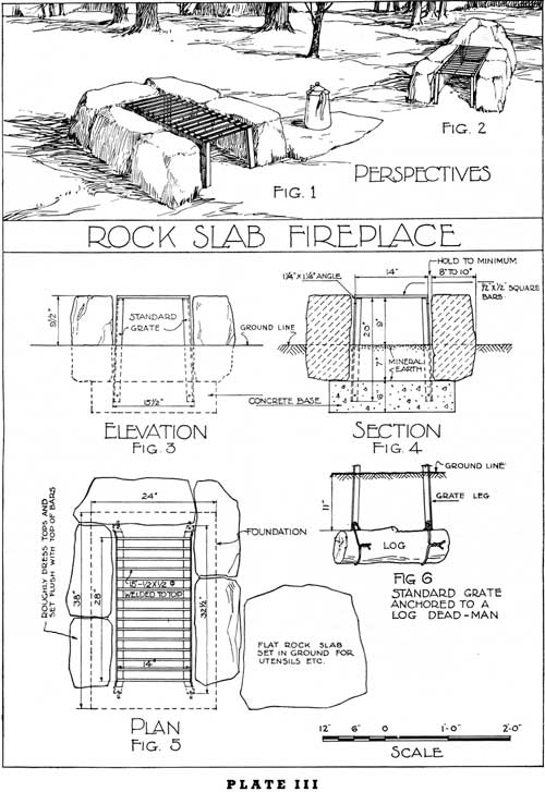
ROCK SLAB FIREPLACE
ADAPTATION TO LOCATION AND USE
This fireplace of simple design and construction is not massive. It is low and inconspicuous and well adapted for picnic use, especially in areas where the fire hazard is small. The open end should be toward the prevailing wind. This type without removable plate is not well adapted for use on campgrounds. (See pl. III-A.)
Since the construction of this fireplace is dependent upon the availability of the desired kind of large stones, laid without mortar, its adaptation to certain sites is limited.
Some question has been raised concerning the problem of maintenance in this fireplace, where the intense heat comes in direct contact with the stone, and especially where it is necessary to douse the fire. If the proper kind of heat-resisting stone is available (as described under "Stone"), the maintenance expense should be no greater than in any other fireplace. Sometimes a sheet iron plate is used on either side of the standard grate in order to protect the stone against the heat (pl. III—A, fig. 2).
DESIGN AND CONSTRUCTION
The grate is entirely separate from the rock. These rocks should be somewhat irregular, with the exception that the ends should be roughly dressed, as should the top (to provide a shelf on which to set pots and pans). The rock used in this fireplace must be of the heat resisting kind. The stones on either side are sunk about one-half of their height into the ground and the tops of the stones are level with the top of the grate. The ends of the stone should be set as close together as possible in order to prevent a cross draft in the firebox. They can easily be replaced if damaged by heat and water.
The grate is anchored by being attached to a concrete block as shown on figure 4, or by being attached to a "log dead-man" (fig. 6). The hearth is usually made of sand or mineral earth and is level with surrounding ground.
The length and width of the firebox is dependent upon the size of the standard grate which is adopted. The height of the firebox should be normal, that is 9 to 12 inches.
VARIATIONS IN DESIGN
Variations in design are shown in figure 2 on plate III, and also in plate III—A. Sometimes the stone at the end may project slightly above the top of the grate to form a raised back which has a tendency to improve the draft.
|
|
PLATE III. (click on image for a PDF version) |
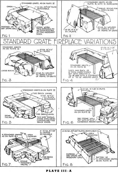
STANDARD GRATE
FIREPLACE VARIATIONS
ADAPTATION TO LOCATION AND USE
This type of fireplace may be developed in a number of ways as shown upon the accompanying plate. Its simplicity of design, permanence of grate, cheapness and ease of construction are important factors which increase its popularity. It is constructed in one form or another for use on picnic areas and on campgrounds, from California to Maine and from northern Washington to Florida. It is a comparatively inconspicuous unit, and for use in its simpler forms (as shown in pl. III, fig. 1; and pl. III—A, figs. 1, 2, and 3) in primitive areas and in high mountain country near timber line, it has no equal. As explained under plate III this unit is not recommended for use in areas of high fire hazard.
The type shown in figure 6 is also not recommended for use in areas where there is any tendency toward vandalism or any rough usage which might knock down the dry stone-enclosing wall. The types shown in figures 7 and 8 are excellently adapted for areas which are used at frequent intervals by rather large groups who frequently have "fish fries." These multiple units provide necessary increase in cooking surface and have proven to be very popular in actual use on a number of recreation areas. In multiple units such as shown in figure 8 the width of the top of the enclosing wall on either side of the large fireplace, may be narrow (approximating 6 inches) because of the reduced requirements for any "warming shelf", and because stones of the width normally used on either side of the single unit fireplace might cause inconvenience in the actual use of the fireplace.
Wherever the single units are used for campground cooking, it is generally desirable that a removable plate be used to cover a portion of the top of the grate as shown in figures 1 and 5.
DESIGN AND CONSTRUCTION
In addition to the comments with reference to the design and construction of this type of fireplace included under plates II and III, this further information may be of value.
This fireplace is sometimes designed as shown in figures 4 and 6 with the long side open to the front. When the fireplace is thus designed it is desirable that the top of the surrounding wall be slightly above the top of the grate and yet not exceeding 18 inches in the height inasmuch as a wall of greater height would not be convenient for use as a seat on which to sit while cooking food on the grate.
The efficiency of this fireplace is greatly increased by the use of the removable top plate.
Whenever a fire-clay brick lining is used in the firebox it is very desirable that the stone masonry construction protect and cover the ends of the fireplace lining as shown on the right-hand side of the fireplace in figure 5. The method of anchoring the standard grate is shown in plate III.
|
|
PLATE III-A. (click on image for a PDF version) |
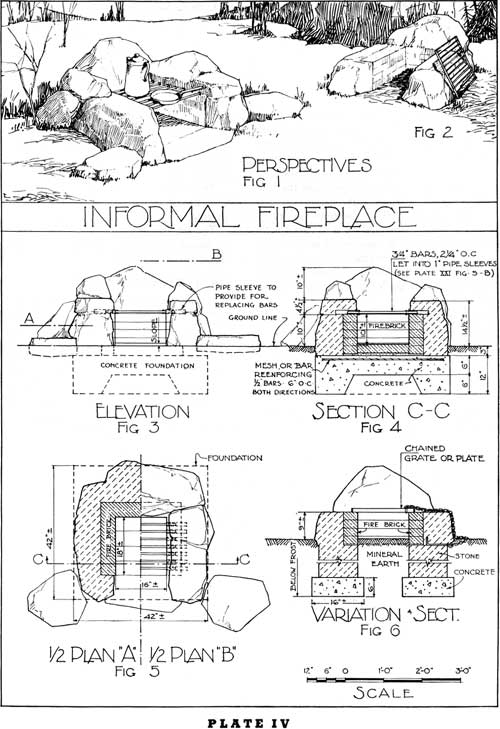
INFORMAL FIREPLACE
ADAPTATION TO LOCATION AND USE
This informal fireplace is well adapted to the natural forest surroundings, especially if the stone used in its construction is carefully selected. In considering this fireplace for any specific area, the designer should determine in advance that stones of the character and size indicated in the drawings are available at a reasonable cost.
This type ought not to be used where the fire hazard is great. It is primarily adapted for picnic areas, rather than for campgrounds, although with a removable solid plate the variation shown in figure 2 could to excellent advantage be used on campgrounds.
DESIGN AND CONSTRUCTION
It has the appearance of dry stone masonry, although it is of solid masonry construction. The joints should be very narrow and raked deeply. The stonework in every way should present a natural appearance. It is important that the side walls be kept as low as practicable in order that the cooking surface be easily and conveniently accessible.
Figure 1 shows flat projecting rocks at the end and sides on which to set cooking utensils.
The foundation should consist of a "floating concrete pad", properly reenforced as shown. In some instances, especially where the hearth is of sand or mineral soil, the foundation under each side should be carried below frost (fig. 6).
The width and length of the firebox may be varied, depending upon the available supply of fuel. The grate consists of 3/4-inch iron bars or pipe set in 1-inch sleeves at either end in order to avoid damage from expansion (pl. XXI, fig. 5).
VARIATIONS IN DESIGN
Figures 2 and 6 show the variations in design. A movable plate or grate may be substituted for the built-in bars, and this plate or grate should be attached securely with a chain. (See pl. XXI, figs. 1, 6, and 7.) If the stone masonry side walls are carried only to the height of the fire-clay brick lining it is necessary to take special precautions in constructing the top of joint between the fire-clay brick and stonework.
|
|
PLATE IV. (click on image for a PDF version) |
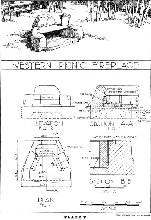
WESTERN PICNIC FIREPLACE
THE fundamental design for this informal fireplace has been developed by the National Park Service and modified in minor detail for use in this volume. This fireplace is not a conspicuous unit, and is most appropriate to the natural forest surroundings where the fire hazard is not abnormally high.
The sides are splayed, as shown in the drawing, and the top of the firebox is covered with a solid plate. For picnic use only, the top might be covered with a removable grate, instead of a fixed plate. It is the author's observation that most recreationists prefer a solid plate, even for picnic use.
The small opening between the back of the plate and the fire-clay brick lining provides an opening which serves as a flue, especially with the back of the fireplace tilted slightly forward. (See fig. 3.) The firebox is lined with fire-clay brick on the sides and bottom. That portion of the bottom of the firebox extending in front of the top plate and on which little or no fire will exist, may be paved with stone.
DESIGN AND CONSTRUCTION
This fireplace may be constructed with a slightly raised hearth, as shown in figure 3, or the hearth may be practically level with the surface of the surrounding ground.
The firebox is larger than the average size. The hearth is raised above the surrounding ground level, and slopes towards the front.
The solid plate is securely attached, as shown in figure 5, and the height of the firebox is approximately 9 inches.
VARIATIONS IN DESIGN
If this unit were used as a fireplace, it would seem practical to have a movable plate or a hinged plate, in which case the plate could be removed, or raised and leaned against the back of the fireplace in order to create a warming fire. In order to create a better draft a procedure is sometimes adopted whereby the back edge of the cast-iron top is turned up at an angle as shown in plate IX, although not quite as pronounced as in plate IX.
|
|
PLATE V. (click on image for a PDF version) |
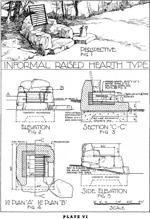
INFORMAL RAISED HEARTH TYPE
ADAPTATION TO LOCATION AND USE
The adaptation to location is similar to fireplace in plate IV. This fireplace should be constructed of informal stonework in order to avoid any formal effect contrasting unnecessarily with the natural conditions. In fact it is advisable in this type with the raised hearth to do a small amount of grading at the back and sides in order to lessen the height of this structure.
The raised hearth makes it possible to develop a higher elevation for the cooking surface on the top of the grate or plate. This added height for the cooking surfaces makes the unit more convenient, and of value for camp sites as well as picnic areas.
The hinged grate and the raised back offer the opportunity to convert this fireplace into a campfire or warming fireplace, which also increases its desirability.
DESIGN AND CONSTRUCTION
This type of fireplace has the stone masonry sides, except the shoulders, level with the top of the fire-clay brick and it also has a raised back against which the hinged grate may rest. Note the suggestion for a projecting stone platform on which to set cooking utensils.
The foundation should be a reenforced floating pad as shown on figure 3.
The raised hearth is constructed of fire-clay brick laid on masonry fill on the top of the concrete pad and the appearance of this fireplace is improved by the construction of a narrow hearthstone (fig. 1) across the front.
The firebox is lined with fire-clay brick. The single rod across the front part of the firebox is used for supporting fuel in order to increase the draft when the fire is being started. The use of this bar is somewhat questionable because an accumulation of ashes would soon offset any advantage gained by the effort to provide this air space, and furthermore, the bar so buried in live coals will eventually "burn out."
The stonework is so constructed that it protects the fire-clay brick and conceals this lining to some extent as seen from the front.
The grate is hinged on a bar which is sunk into "sleeves" inserted in the stonework (pl. XXI, fig. 5, plan B).
The hinge rod (pl. XXI, figs. 2 and 3) provides a method for securely fastening the grate or plate to the fireplace in a simple and solid manner. This provision also makes it easier to remove the ashes from the firebox. The grate, as hinged, may be raised and supported against the back of the fireplace in order to create the effect of an open fire.
VARIATIONS IN DESIGN
For variations in design, refer to plate VII.
|
|
PLATE VI. (click on image for a PDF version) |
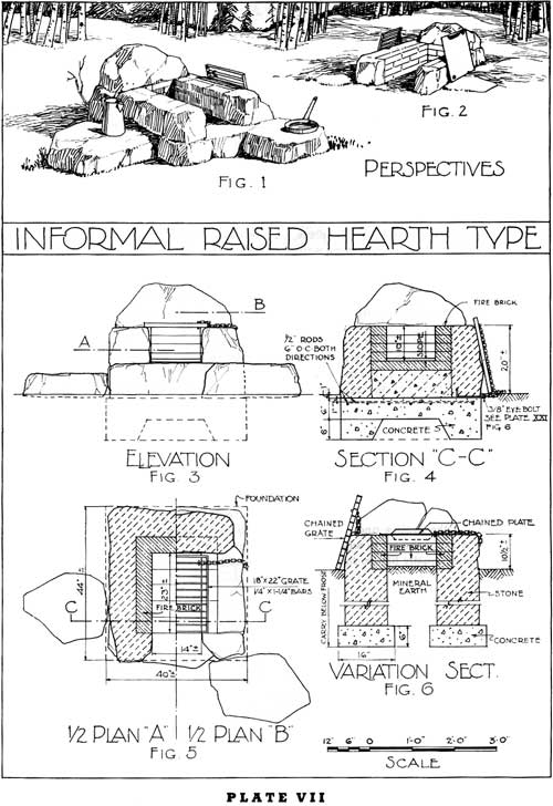
INFORMAL RAISED HEARTH TYPE
ADAPTATION TO LOCATION AND USE
This type has the same problems concerning adaptations to location and to use as relate to the fireplace shown in plate VI.
DESIGN AND CONSTRUCTION
The slabs of stone on which to set cooking utensils, and related to the fireplace as indicated in the sketch, have a tendency to more directly "tie" this feature to the ground. The single capstone across the back of the fireplace extends over and is set flush with the face of the fire-clay brick lining in order to improve the design and the construction. The front corners of the fireplace are returned in such a manner that they partially conceal the fire-clay brick lining.
The hearth if raised to a height approximately 12 inches above the ground level, would bring the cooking surface at the top of the grate or plate to a height of 22 inches, which would make the unit more convenient for camp use, and more massive.
This entire structure (excepting the single slabs of rock at either side) should rest upon a reenforced concrete floating pad foundation. The flanking rocks are buried slightly in the ground.
The hearth should be constructed of fire-clay brick laid on a masonry fill on lop of the concrete foundation. There may or may not be a projecting stone hearth at the front of the fireplace.
The fire-clay brick is anchored by the cap stone across the back and is carried only to the level of the stone masonry wall on the sides. In this method of construction, the joint between the fire-clay brick and the stonework should be very carefully constructed in order to avoid the possibility of water entering between the fire clay brick and the stonework, thus causing damage during the winter months.
The success of this fireplace depends upon the use of large units of stone of a uniform character, and upon a careful treatment of the joints in order to conceal them as much as possible. The flanking rocks which are not set upon any foundation should be entirely free from the fireplace structure, so that in heaving and settling under frost action no damage will be done to the stone masonry.
VARIATION IN DESIGN
A variation (figs. 2 and 6) indicates the hearth lowered to the ground level with the fire-clay brick in the hearth omitted, and sand or mineral earth substituted in its place. In this variation in design the foundations under the side and rear walls should be carried below the frost line.
|
|
PLATE VII. (click on image for a PDF version) |
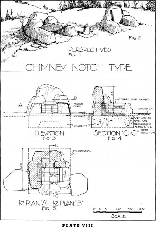
CHIMNEY NOTCH TYPE
ADAPTATION TO LOCATION AND USE
Because of the raised back and the chimney notch effect which takes the place of a chimney, when a solid plate is used for, the top, it is essential that this fireplace, so far as is practical, be oriented to take advantage of the prevailing wind.
This fireplace, especially with the solid plate, is adapted for use on campgrounds, especially if the hearth is raised to make the top of the plate approximately 14 to 16 inches above the ground.
This type is a cross between an open fireplace with a solid back (pl. VII) and the low chimney type (pl. X). Its distinct advantage is that it is easily converted from a fairly efficient cooking fireplace with an iron plate cooking surface, into an open reflecting fireplace for campfire use in the evening.
DESIGN AND CONSTRUCTION
Converting this unit from a cooking fireplace to a campfire is accomplished by tilting the top plate against the notch with the narrow side resting on the hearth at the back of the firebox, as shown in figure 2.
The dimensions of the firebox and of the top plate are so related that the plate when stood on its narrow side will easily fit into the firebox as shown in figure 2. The depth of the firebox from front to back should be 2 inches less than the width. In order to have the plate set on the top of the fire-clay brick lining, the plate should be 4 inches longer than the width of the firebox, thus allowing a 2-inch overlap on each end of the plate. In this instance, the width of the firebox is 16 inches and the depth of the firebox is 14 inches. The length of the plate is 20 inches and the width of the plate is 14 inches.
This structure is also supported on a reenforced concrete floating pad. The hearth is constructed of fire-clay brick, and the firebox is lined with fire-clay brick, including the chimney notch. The stonework partially conceals the fire-clay brick, as shown in the drawing.
The grate or plate should be removable, with the flange on the front edge of the plate turned down, and the flange on the rear edge turned up, and it should be attached by a chain to the stonework. The bent flanges will tend to prevent sagging. (See pl. XXII, fig. 4.)
VARIATIONS IN DESIGN
The only variation in design which seems of sufficient importance is the raising of the hearth where this unit is used primarily for campgrounds.
|
|
PLATE VIII. (click on image for a PDF version) |
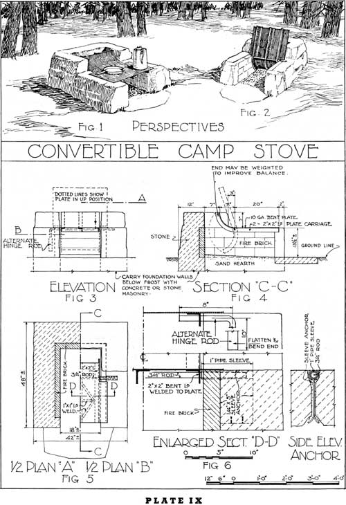
CONVERTIBLE CAMP STOVE
ADAPTATION TO LOCATION AND USE
This camp stove is an unusual type, the fundamental idea for which was developed by region 1 of the United States Forest Service. It is especially well adapted for use in the forest areas, where camp stove cooking facilities are required. The unit is low and, if carefully constructed with an appropriate type of stone found in the immediate locality, this stove is most acceptable.
The necessity for a chimney, which adds to the massiveness of any camp stove, is avoided by the hinged plate shown in figure 4. In the areas of high fire hazard, it is difficult in this stove to control the sparks, which in the type shown on plate X can be easily controlled by a spark arrester in the low chimney.
This stove is easily converted into a warming fire by raising the plate, as shown in figures 2 and 4.
Most camp stoves are too massive for use in open and semiopen areas, and are only adapted for practical use in connection with camp units where natural screen planting between the units exists. The necessity for screen planting where this stove is used is not as great as where the larger and more imposing units are used. This type of camp stove seems to have excellent possibilities as a most useful unit easily converted from picnic use to camp use or vice versa.
DESIGN AND CONSTRUCTION
The plate may be of cast iron or of 10-gage boilerplate, bent to fit the design of the stove as shown in figures 1 and 4. If a cast-iron plate is used, the front part of the plate should be counterbalanced by additional weight in the curved portion of the plate back of the hinge in order that the sudden dropping of the plate on the top of the brickwork will not injure the plate. If 10-gage boiler plate is used for the top of the fireplace, it is not necessary that any counter balance weight be used.
The hinge on which the plate revolves is located as shown in figure 4 and is anchored in the stone masonry as shown in figure 6. The increased width of the front portion of the plate (figs. 1 and 5) allows the plate when raised to rest against the side walls, as shown in figure 2.
The hearth should slope slightly to the front, and at the front edge it may be level with the surrounding ground. If, in exceptional instances, the camper desires a more convenient height for the top of the plate, the hearth may be raised approximately 6 inches above the ground level.
The underside of the plate is reenforced with 2- by 2-inch angle irons, which are welded to the plate to prevent warping and possible sagging. These angles are pierced to allow the hinge rod to pass through.
|
|
PLATE IX. (click on image for a PDF version) |
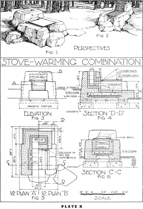
STOVE-WARMING COMBINATION
ADAPTATION TO LOCATION AND USE
This fireplace approaches the camp stove type and is excellently adapted to campground use. These larger types are not recommended for the open and extensive picnic areas requiring a number of cooking units. The ideal location for such fireplaces is one where the ground level may be raised at the sides and the back to reduce apparent height.
The low chimney in which a spark arrester may be inserted, if necessary, is added protection against any fire hazard, especially in the timber areas of the West.
The use of this unit as a cooking stove, or as a warming fire, is easily accomplished by raising the hinged plate and the grill as shown in figure 4.
DESIGN AND CONSTRUCTION
The design includes provision for a grill or grate and/or a solid plate, both of which are hinged on bar hinges as shown in plate XXI, figure 4. When the top grate and plate are thrown back against the chimney, this unit is converted into a warming fireplace. For use in cooking, either the grill or the plate may be used.
Where fuel economy is an important factor, the shelf shown in figures 4 and 5 may be lengthened as indicated by the dotted lines, thus reducing the depth of the firebox proper while retaining the same area of cooking surface.
The stone platforms on which to place cooking utensils may be constructed as shown in the sketch.
The foundation for this type of fireplace should be carried below the frost line and the fire-clay brick hearth should be supported on a reenforced concrete slab, as shown on this drawing. The firebox is lined with fire-clay brick laid as stretchers. The top plate ought to be 10-gage sheet iron. It is not necessary to reenforce this plate because the plate will rest directly on top of the grate.
The stonework must be laid in an informal manner with carefully selected native stove.
The low chimney is lined with fire-clay brick, laid flatwise. An arch constructed of fire-clay brick extends across the flue opening. The top of this arched opening is slightly below the level of the plate.
VARIATIONS IN DESIGN
Where steelwork is available at no abnormal cost, two 3- by 3-inch angles with 1/4- by 9-inch plate riveted to the under side may replace the arch and will improve the appearance.
The raised hearth may be omitted if the lower elevation of the top is acceptable and the height of the entire mass will thus be reduced approximately 8 inches.
|
|
PLATE X. (click on image for a PDF version) |
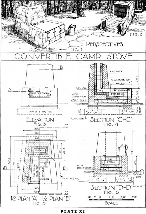
CONVERTIBLE CAMP STOVE
ADAPTATION TO LOCATION AND USE
This type is primarily a camp stove, although it may be used as a campfire. The simpler units (pls. IV, V, and VIII) are appropriate for the natural forest areas. There is, however, in many campgrounds, especially in the larger timber, a definite need for this convertible unit which eliminates undue fire hazard, provides for cooking and for warming fire use, and increases the convenience of everyday use in a camp.
These units ought to be so located that a screen of natural growth will separate one from the other.
This camp stove, together with the stove shown in plate XI-A, figure 4, are excellently adapted to campground use.
DESIGN AND CONSTRUCTION
It should be constructed with an interesting texture of informal stonework and should tie naturally to the surrounding ground.
In addition to the sand or gravel area which naturally should surround any campfire or camp-stove unit, there might well be a few flagstones immediately in front of this camp stove.
The foundation walls should extend below frost, in order to avoid the danger of uneven settlement due to the excess of weight at the chimney end of the camp stove.
The chimney is lined with fire-clay brick and the firebox is lined to the height of the side walls. The firebox is entirely enclosed by the solid top plate and the single door or double doors across the front.
The solid top plate extends 2 inches over the brickwork on either side and it is hinged at the rear of the firebox as shown in figure 2. In order to convert this stove into a campfire, the doors are opened and the top is thrown back against the chimney. A certain amount of heat will continue to go up the chimney unless a damper is installed to control the draft.
The danger of warping is decreased by the welding of two 1 by 1 inch angles across the underside of the top plate (pl. XXII, fig. 4).
The chimney approximates 3-1/2 feet in height above ground level. It may be lined with lava rock, or it may have a terra-cotta flue lining in place of the fire-clay brick. It is very desirable that a spark arrester be inserted in the top of the chimney, especially if the fire hazard is very great.
VARIATIONS IN DESIGN
It is entirely practical to have the firebox with the sides parallel (pl. XI—A, fig. 4), rather than to have the front of the firebox wider than the rear, although the splayed sides reflect more heat when used as a warming fire.
If the front doors are omitted, then it will be necessary to install a damper in the chimney in order to properly control the draft.
In figure 4, the height of the top plate above the ground is approximately 16 inches. This top plate may be lowered approximately 4 inches by omitting the raised hearth and thus leaving a total height of approximately 12 inches between the surface of the ground and the top of the plate, with chimney lowered proportionately.
|
|
PLATE XI. (click on image for a PDF version) |
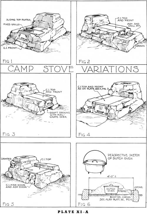
CAMP STOVE VARIATIONS
UPON this plate there are shown a few variations of camp-stove designs some of which are excellent for certain uses and some of which do not seem to be practical except under conditions which impose unusual requirements upon the camp-stove design.
The details for design of these stoves are not covered in a special drawing because those desirable features are covered directly or in modified form by parts of drawings on other plates.
Each of these variations in type is discussed under its individual heading.
The desirable stoves for campground use are those shown in plates III—A, VII, VIII, IX, X, and XI, or variations of some of these types. Figures 3 and 4 in plate XI—A especially when providing for a combination top grate and top plate may be adapted for use as a fireplace or as a camp stove.
CAMP STOVE WITH GRATE AND SLIDING TOP PLATE
The usual method of designing combination op grate and top plate is as shown in plate X or as is shown in plate VII. In the first instance the plate is hinged over the grate and in the second instance the plate is removable.
Figure 1 shows a suggested method of providing a sliding plate which may be pulled to one side as shown in the drawing, thus exposing the grate for broiling and grilling.
This type of design is not simple. Such stoves are expensive to construct. The top plate if too thick decreases the heating efficiency to a very marked extent. This stove does not seem to have a definite place for campground use in the forests and is therefore not recommended.
CAMP STOVE WITH ASHPIT AREA IN FRONT OF FIREBOX
This type of stove is similar in design to the stove shown in figure 4 with the exception that the shallow enclosed pit in front of the firebox is added to this unit to serve a dual purpose as follows:
(a) To be used as an ashpit in areas where there is abnormal fire hazard. (There seem to be very few areas where this abnormal precaution is necessary especially if a hearth of flagstone or mineral earth is provided immediately in front of the firebox.)
(b) To provide a space into which to pull the live coals so that a toaster or a grill may be placed across the top on which to broil steak and other meats.
This added feature constructed as shown in figure 2 makes an abnormally long unit of a camp stove. This ashpit area is in no way essential if the combination grate and plate is used for the top.
CAMP STOVE WITH GRATE IN BOTTOM OF FIREBOX
In some areas where a condition of excessive moisture (rain or fog) prevails it is sometimes desirable to so construct the camp stove that a bottom draft may be procured through a grate in the bottom of the firebox. Such a type of design is not generally recommended except where the condition of the wood used for fuel is so affected by the moisture that this additional bottom draft is necessary.
CAMP STOVE WITH SOLID TOP PLATE
One of the most practical camp stoves is that shown in figure 4. The efficiency of this stove might be much increased if it were so designed that a combination grate and plate properly hinged as shown in plate X were used. The solid plate on the top of this stove does not permit any use for broiling over a grate and neither does it provide opportunity for use as a fireplace with the top plate raised as shown in plate XI, figure 2. It is also desirable in these camp stoves to provide a damper preferably in the chimney as shown in plate XI—A, figure 5.
CAMP STOVES WITH THE DOOR ON THE SIDE
In some campgrounds it seems desirable to adopt a type of camp stove such as is shown in plate XI—A, figure 5. The advantages claimed for this stove are the following:
(a) An economy of fuel because the firebox is very small in proportion to the cooking area on the top of the stove. The heat under a portion of the top plate is produced by the flames which travel under this plate to the flue, in which a damper is constructed.
(b) A cooking ledge is provided on the front of the stove to be used for warming purposes.
(c) A "windbreak wall" may be constructed on the windward side to protect the top from any abnormal currents of air caused by prevailing winds, especially in the higher mountain country where a strong wind generally prevails, especially in the late fall and early spring.
This stove, if well constructed and kept sufficiently low by eliminating the ashpit under the firebox, is an appropriate unit in the forest surroundings. It is undoubtedly more expensive to construct than the more simple type of stove shown in figure 4.
DUTCH OVENS
The dutch oven is probably one of the simplest and most effective method of cooking certain foods.
In areas of considerable fire hazard and especially in the primitive areas, it is desirable to construct a small pit, similar to a campfire circle, surrounded by a row of stones which will confine the fire within a specific area.
The success with which a dutch oven may be used for cooking depends very largely upon the experience and ability of the person who is using the oven. The general method of using this oven is that of building a fire in a small campfire circle (fig. 6). After this fire has burned sufficiently long to produce a liberal bed of live coals, these coals are so arranged that the dutch oven, containing the meat or other food to be cooked, can be set firmly into the bed of coals. After the cover has been securely fastened, the entire dutch oven is completely covered (fig. 6) with coals and left thus buried in a bed of coals and ashes for the length of time necessary to properly cook the meat or other food to be placed in the oven.
|
|
PLATE XI-A. (click on image for a PDF version) |
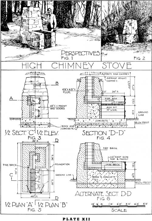
HIGH CHIMNEY STOVE
ADAPTATION TO LOCATION AND USE
The high chimney stove has little or no place in the national forest areas, because of its massiveness. The discussion covering camp stoves would not be complete without including this type of stove because, in a few locations where the fire hazard is abnormally high and where it is possible to provide an adequate screen between the different camp units, such a stove might be used. Its general use should be discouraged.
The cost of constructing such a unit seems to be out of proportion to the results which are obtained as compared with the results that can be obtained in the construction of the simpler types of definite camp stoves shown particularly in plates IX, X, XI, and XI—A, figure 4.
This feature more nearly approaches the conveniences of the stove at home and, for this reason alone, it deprives one of some of the satisfactions which come from a new kind of recreational activity in the natural out-of-doors.
DESIGN AND CONSTRUCTION
This unit becomes increasingly objectionable unless the stone used in its construction is carefully selected and equally carefully laid, in order to avoid some of the objectionable textures of stonework illustrated in plates XXIV and XXV.
The foundation on which this stove rests should be carried below the frost line, as shown in figure 4, and it may be constructed by placing rocks in the concrete to lessen the amount of concrete required.
The stove is provided with a definite firebox and an ashpit, separated with a grate. The draft is controlled by a damper in the chimney and oftentimes by a damper in the door at the front of the firebox. The doors and the top plate are generally made of cast iron.
As shown in the drawings, the firebox and the flue should be carefully lined with fire-clay brick or other equally acceptable material.
The author has observed some of these stoves, in which the space between the back of the fire-clay brick lining and the stone masonry is left as an air space or is filled with asbestos. The author questions the necessity for this provision in the design of this type of camp stove. In any event, the top of this space should be thoroughly sealed to prevent the entrance of water.
|
|
PLATE XII. (click on image for a PDF version) |
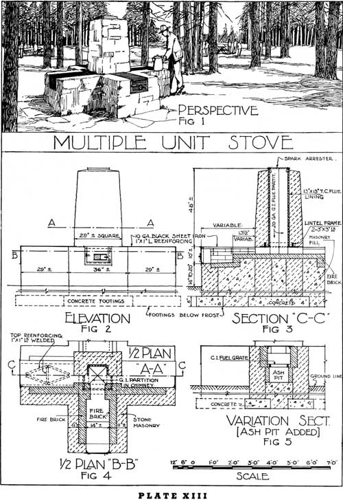
MULTIPLE UNIT STOVE
ADAPTATION TO LOCATION AND USE
The multiple unit is a massive structure which has, with rare exceptions, no reason for existence on a national forest, and is in reality a camp stove adapted only to picnic area use. This type of multiple unit is of greatest value in connection with areas used intensively and by large organized picnic groups. It has little value on areas used for small family picnics, or on campgrounds.
It may be used in multiples of two, three, or four, as shown in figure 1. The most practical design is in multiples of two, which greatly reduces the congestion around the cooking space.
It is very seldom that a multiple unit of this kind would be used by campers, except those who live at resorts, in connection with which there are small cabins constructed close together.
This type of stove in multiple units is excellently adapted to some of the areas where there is intensive activity in winter sports.
DESIGN AND CONSTRUCTION
The foundation under these structures should extend below the frost line and the hearth should rest on a masonry fill. The hearth and the firebox should be paved with fire-clay brick.
The efficient design of these units requires a minimum length for the firebox, and a narrow entrance to the flue, creating a considerable additional warming area, as shown in figure 3. Under this type of design, the flames and the hot gases are forced through the narrow passage over the shelf which is directly under the cooking top, thus making the entire surface of the cooking top available for use.
In this drawing, a 10-gage iron top is indicated, reenforced with 1 by 1 inch angle irons welded to the undersurface as shown. The use of a thinner gage may cause buckling and sagging, and to date the information concerning this problem is not sufficiently adequate to determine the result which would occur by using any thinner material.
The high chimney may have a terra cotta flue lining, although fire-clay brick will serve equally well. Sometimes the single flue is made sufficiently large to meet the requirements of the multiple units which it serves and it should then be divided into the required number of smaller flues of the proper size. This encourages a more efficient operation by shutting out the cold air which would otherwise be drawn from the stoves not in operation.
VARIATIONS IN DESIGN
Sometimes an ash pit may be constructed under the firebox, as indicated in figure 5 and as shown in plate XII, figure 4.
|
|
PLATE XIII. (click on image for a PDF version) |
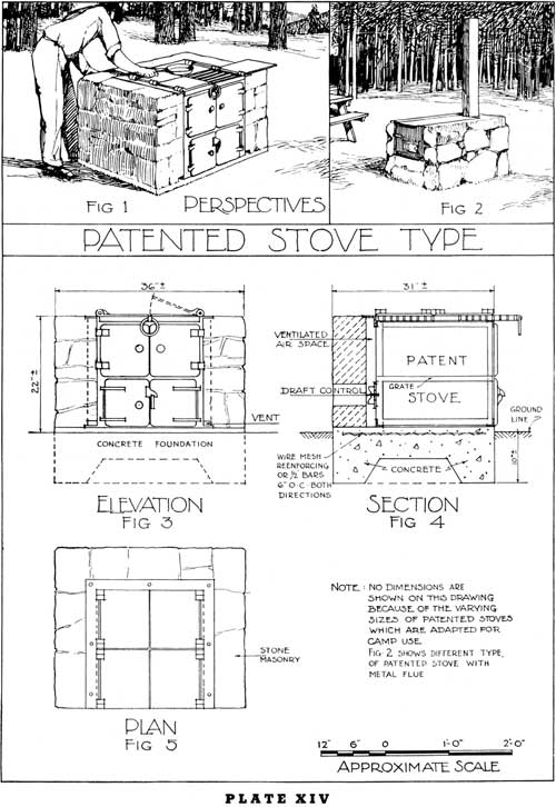
PATENTED STOVE TYPE
THERE are a number of types of patented stoves adapted for use on campgrounds and picnic areas. These stoves are apparently designed primarily for cooking purposes, and the author has seen few of these patented stoves which, either before or after being covered with a stone masonry "shell", seem appropriate in a forest setting. They are excellently adapted to the more intensively used camp ground and picnic areas, near the centers of considerable population. The shape and appearance of these units are such that they do not seem to blend happily with the natural surroundings.
DESIGN AND CONSTRUCTION
Many of the patented stoves do not have a chimney. They are designed with an opening at the back of the firebox. The draft control, firebox, hearth, top grate or plate, and other mechanical features vary with each type of patented stove, and the stone masonry work should conform to the particular type of construction.
Unless the patented stove has a metal back and sides, a fire-clay brick lining should form a part of the enclosing masonry shell.
It is customary to provide, in the construction of these stoves, a ventilating air-space (see fig. 4), between the metal and the masonry. This air-space ought to be thoroughly sealed at the top.
The sketch in figure 2 shows another type of stove enclosed in a stone masonry covering. The use of this type of stove with the square metal chimney as shown in the sketch, gives rise to considerable difference of opinion concerning the appropriateness of this kind of a chimney to the forest surroundings.
There may be a few instances in which it is more desirable to use an inconspicuous, although distinctly artificial chimney of this type than to construct a massive chimney which is equally as far out of proportion to the camp stove. In general, the use of this type of stove, with the chimney as shown in the sketch, ought to be discouraged in spite of its practical value.
|
|
PLATE XIV. (click on image for a PDF version) |
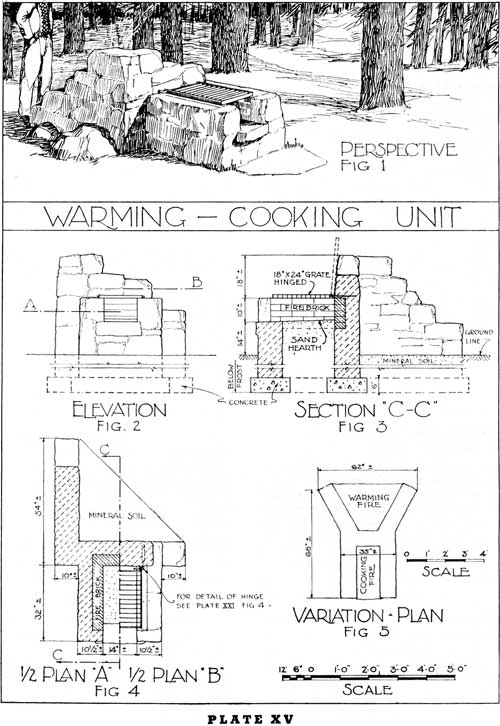
WARMING-COOKING UNIT
ADAPTATION TO LOCATION AND USE
The warming-cooking unit is generally not adapted to areas where the fire hazard is great.
These units may be used, (a) in connection with shelters (pl. XIX, figs. 1 and 5), (b) in connection with swimming pools on campground areas, and (c) on campground and picnic areas. The two most logical ways in which to combine the campfire and the fireplace, or camp stove, are shown in figures 4 and 5 on the accompanying plate.
When these units are used in connection with shelters, it is the usual practice to face the camp fire toward the shelter, as shown on plate XIX, figure 6, and to have the cooking unit on the side farthest from the shelter. In this way the interior of the shelter receives the full benefit from the campfire, the purpose of which may be to warm and to light the interior of the shelter.
The warming fire by itself is another feature which is considered in connection with the discussion of plate XX.
These units are adapted only to areas where there is an adequate supply of fuel easily available.
DESIGN AND CONSTRUCTION
The design of the stonework should be very informal and rustic. The foundation under these features should extend below frost. It may be advisable to line the sides of the warming fire area with fire-clay brick or lava rock in order to protect the stone masonry from damage by the intense heat. The fire-clay brick lining should, however, be avoided if possible, even to the height of a few courses, because it is unsightly and unnatural in a fireplace of this type.
The top of the grate or the plate may be lowered to a height of 14 to 16 inches above the ground.
VARIATIONS IN DESIGN
The variations in design are shown in figures 4 and 5.
|
|
PLATE XV. (click on image for a PDF version) |
BARBECUE PITS AND BARBECUE OVENS
GENERAL CONSIDERATIONS
While barbecue pits and barbecue ovens have been in use during a considerable period of years, the specific information relating particularly to the design and construction of these features is rather difficult to procure. The three types, as follow: (a) Barbecue pit (pl. XVI), (b) free standing barbecue oven (pl. XVII), and (c) hillside barbecue oven (pl. XVIII), shown in the accompanying plates, include the range of facilities normally used for barbecuing.
The word "barbecue" (both as a noun and a verb) is used in connection with the roasting of the whole carcass of an animal, or, for convenience in handling, the carcass is sometimes quartered or cut into even smaller portions.
For the purposes of this bulletin, only the medium-sized barbecue pit and oven is shown in the detailed drawings. The larger barbecue pits and ovens, when required, are designed in accordance with the same plans, and the size is computed in accordance with the requirements of use, as hereafter explained.
LOCATIONS FOR BARBECUE PITS AND BARBECUE OVENS
These features are of practical use only where large numbers of people congregate in the open to eat at the same time. The specific location selected for barbecue pits, in particular, must be well drained, because any fire built in the bottom of a pit would not operate efficiently if free moisture were present to choke out the fire. The presence of an abnormal amount of moisture would cause the formation of steam, and might even cause an explosion.
There should be a reasonably large open and flat area adjacent to the barbecue pit or oven, in order that all of the people who are likely to gather for any such occasion may be accommodated.
The construction of barbecue features is expensive, and the successful operation of the barbecue pit or barbecue oven consumes a large quantity of wood. These features should therefore be constructed only where the supply of natural fuel is plentiful, and where there is a real demand for the use of this kind of a cooking facility.
In Puerto Rico, where the climate permits outdoor activity during the entire year, and where roast pig is considered a real delicacy, barbecue pits and ovens are almost a necessity in connection with public recreation areas.
ADAPTATION TO LOCATION AND USE
Barbecue facilities are adapted to the roasting of an entire carcass or to one or more large portions of meat at the same time.
The successful operation of a barbecue pit or oven requires an experienced individual who understands this method of cooking meat. Inexperienced operators may easily spoil meat by under- or over-cooking it through incorrect operation of the barbecue pit or oven.
The real purpose of the barbecue pit and barbecue oven is that of slowly cooking a considerable quantity of meat for a period of time which may vary from 8 to 12 hours, and sometimes 24 to 36 hours, depending upon the size of the carcass and the degree of heat.
The maximum success in barbecuing meat is procured when the pit or oven can be made practically airtight and thus resembling a fireless cooker. Unless the pit is practically airtight, the meat is very apt to burn.
OPERATION OF BARBECUE PIT AND OVEN
While barbecue pits and ovens possess the advantage of providing facilities for the cooking of a considerable quantity of meat at one time, these features also have the disadvantage of being difficult to operate conveniently, because of the intense heat and the unwieldiness of the ordinary-sized carcass of a steer or other animal, unless the barbecue feature is well designed for practical operation. The practical methods of handling large pieces of meat are explained in the text which accompanies the following plates.
DETERMINING SIZE OF BARBECUE PIT OR OVEN
The actual size of the barbecue pit or barbecue oven is determined by the number of people for whom a supply of meat must be barbecued at any one time. In determining the practical size for any specific area, it is necessary first to determine the number of people who will occupy, at any one time, a recreation area provided with barbecue facilities.
It is generally estimated that 1 cubic foot of meat weighs approximately 40 pounds, and that the allowance per person will vary from one-half to 1 pound, depending upon the extent to which other foods are supplied for any specific occasion. The estimated amount of meat consumed per person will also depend upon the percentage of bone which remains in any carcass to be barbecued (allowance of 20 percent is usually made for the bone, unless the section of beef has been boned) and it will also depend upon the amount of waste due to undesirable cuts and excessive fat. The skill and ingenuity of the operator in properly cooking and properly cutting the meat when served also is a factor.
It is further generally assumed that there ought to be approximately 12 inches of clearance between all confining surfaces and the meat. A cubic foot of meat would therefore properly fit into a barbecue pit or barbecue oven with dimensions 3 feet wide, 3 feet long, and 3 feet high, making allowance for the depth of ashes which would remain in the bottom of the barbecue pit, but no allowance for any ashes in the bottom of the barbecue oven (inasmuch as the ashes would be removed from the bottom of the oven before the meat is put in place). This size of meat would therefore serve from 40 to 80 persons, depending upon the conditions above stated.
On the basis of this analysis, the number of people who could be served at any one time through the cooking facilities of the barbecue pits and ovens in the following drawings would be approximately as follows:
Barbecue pit shown in plate XVI (with capacity of approximately 310 pounds)—number of people to be served approximates from 350 to 600.
Plate XVII—number of people to be served approximates from 250 to 475.
Plate XVIII—number of people to be served approximates from 450 to 875.
MATERIALS OF CONSTRUCTION
The materials of construction are covered in the detailed discussion which accompanies each of the following plates.
In general, it is desirable that the barbecue pit and barbecue oven should be properly lined with fire-clay brick, although a lining of dense volcanic rock would also serve in place of the fire-clay brick.
METHOD OF OPERATION
In the successful operation of a barbecue pit or barbecue oven, the meat is cooked by the heat which is retained in the surrounding walls and floor of the barbecue pit or oven.
There are several ways of preparing meat for barbecuing. The most common way is to take the cleaned and skinned carcass and roast it whole, without removing any bones.
Oftentimes, larger animals are quartered, or cut into even smaller portions, each weighing from 40 to 50 pounds, to facilitate the ease of handling. When the meat is thus cut, the individual pieces should be of approximately equal size, in order that each piece may cook uniformly. The usual procedure is to tie the pieces of meat with heavy twine, like rolled roasts of beef.
Sometimes a method of barbecuing called steam roasting is adopted, in which case the pieces of meat are wrapped in wax paper and covered by damp clean sacks before being placed in the pit or oven. This method of procedure preserves the juices in the meat and gives a less-pronounced roasted taste.
It is necessary, in cooking the meat, that the cover to the pit, or the doors to the oven, should be replaced and the cooking space sealed as tightly as possible immediately after putting the meat in place.
An exclusion of air from the pit and the oven during the cooking process is very important, in order to insure that the meat will be brown in color, tender, and not burned, and also in order that the meat shall retain its natural flavor.
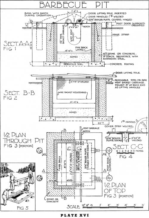
BARBECUE PIT
THE barbecue pit offers the simplest means of maintaining the necessary degree of heat for barbecuing. The Indians and the early settlers discovered long ago that a hastily dug hole or trench, in the bottom of which were placed large stones, and on the top of which had been built a hot fire, was an excellent means of cooking large portions of meat.
Wherever the ground is sufficiently well drained to make practical the construction of a pit, the barbecue pit is preferable to the barbecue oven, because the natural ground serves to insulate the area surrounding the pit and preserves the maximum amount of heat.
The walls of the pit may be made of concrete or stone masonry and the sides of the pit lined with fire-clay brick, as shown in plate XVI. The floor of the pit should be of pervious soil to provide ready drainage and, if desirable, to imbed in this soil a few larger stones, in order to retain some of the heat in the bottom of the pit.
A fire may readily be made in the pit by inserting one or two posts in an upright position, and heaping the wood around these posts. After the wood has been put in place, the posts are then withdrawn and a small amount of kerosene or other oil may be poured into the hole, and the wood ignited by a burning torch dropped into the hole.
This fire thus started in the pit (depending upon the size of the pit) should be kept burning for a period of 8 or 12 hours or longer, in order to thoroughly heat the bottom and side walls, and to create a bed of ashes over the bottom of the pit.
After the fire thus maintained has thoroughly heated the pit, the carcass or chunks of meat are put into place in a wire basket, as shown in figures 1 and 5 of the accompanying plate. The cover to the pit may consist of a pair of hinged boiler-plate doors, reinforced with 2- by 3-inch angles to prevent any sagging of the doors.
As shown in the drawing, these doors have large handles through which a pole may be inserted to facilitate lifting. Free standing posts support the doors when the pit is open and prevent straining of the hinges.
The basket is made of woven wire and is suspended from two pipes, which rest in grooves at the ends of the wall, as shown in figures 2 and 3.
After the meat is put in place, the covers to the pit are closed and earth is banked over the top of the covers to prevent any unnecessary loss of heat and to increase the airtight condition of the pit.
When the pit is not in operation, provisions should be made so that the covers may be locked, in order to prevent vandalism and to avoid accidents.
In many places in the western part of the country, food is cooked in a "dutch" oven, which is a small unit (pl. XI—A), operating on the principle of the barbeque pit. The container, which resembles a large kettle, is made of cast iron and has a tight fitting cover. A fire is built, and a liberal bed of live coals is produced by burning the fire for the desired length of time to produce enough coals so that this "dutch" oven may be partly buried in the coals and the remainder of the coals may then be heaped against the sides and over the top of this container in which the food is placed. This method of cooking requires considerable skill to know the length of time which will be required in order to properly cook different kinds of meat and other food. The "dutch" oven, so-called, can usually be purchased from hardware stores in the western part of the country, and it is in general use by the sheep-herders and others who wish to have an efficient and compact unit in which to cook food.
|
|
PLATE XVI. (click on image for a PDF version) |
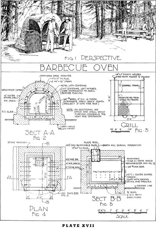
BARBECUE OVEN
IN SOME locations, where the natural drainage facilities are not acceptable for barbecue pits, it is advisable to construct barbecue ovens.
The most desirable type of barbecue oven is the type such as is shown in plate XVIII, which is constructed in a slope so that the front of the oven is the only evident part of the artificial construction.
It is necessary, however, in some locations, on the flat areas, to construct a barbecue oven entirely above ground, as shown in plate XVII. The question of proper insulation for conserving the maximum amount of heat within the oven, is a primary consideration. One method of construction, in order to accomplish this result, is shown in the detailed drawings in plate XVII, through which method of construction an air space is provided between the fire-clay brick lining and the outer stone masonry shell.
In these ovens, not only the side walls and the roof, but also the floor, is of fire-clay brick. This fire-clay brick floor is laid upon a reenforced concrete base. After the oven has been thoroughly heated, the ashes are raked from the oven before the meat is placed in the oven on the grill which is shown in the detailed drawing.
In this type of feature, the stone-masonry walls must be carried below the frost-line.
The constructing of this type of barbecue oven requires that the fire-clay brick shell shall first be constructed on the concrete foundation. The centering is then put in place, and the outer stone masonry shell is constructed. The wood members used for the centering are thoroughly soaked before being put in place, so that there can be no subsequent swelling which might injure the structure.
It does not matter what happens to this centering after the construction has been completed. In all probability it will shrink and drop out of place, and it will probably char, without affecting in any perceptible degree, the insulating qualities.
In all barbecue ovens, a chimney is necessary. This chimney will have a flue lining, which should be supported on iron straps, as shown in figure 2. These straps are supports for a removable plate, which is put in place after the fire has been removed. In order to properly seal this part of the oven, natural earth is placed on the top of the plate in the flue, as shown in figure 5.
The grill, of reenforcing mesh (fig. 3), on which the meat is placed is supported by 3/8-inch rods, as shown in figures 2 and 5.
After the meat has been placed in the oven, the front opening is closed with a double covering consisting of an inner shield of sheet-iron (fig. 5), which is locked in place during the actual cooking operation. A small amount of natural earth, placed at the bottom of the inner shield, may help to seal this opening.
The doors are then closed and locked, and it might be advisable to place a small amount of earth against the bottom of the doors.
When not in use, the main outside doors should be kept fastened with a padlock.
|
|
PLATE XVII. (click on image for a PDF version) |
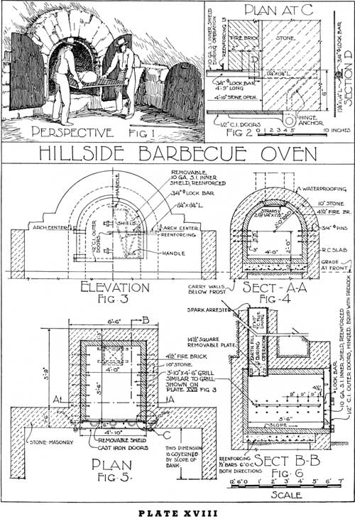
HILLSIDE BARBECUE OVEN
THE hillside barbecue oven, where natural conditions of topography are adapted to the construction of this type of oven, is preferable to the free standing oven shown in plate XVII because this unit is not as conspicuous.
Construction of the hillside barbecue oven is substantially the same as of the free standing oven, except that the natural earth covering makes it unnecessary to provide the insulating air space between the back of the fire-clay brick lining and the inside surface of the stone masonry shell.
|
|
PLATE XVIII. (click on image for a PDF version) |
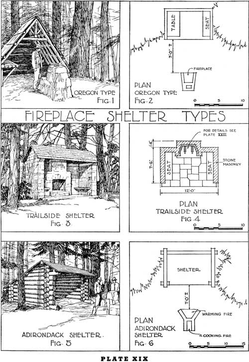
FIREPLACE SHELTER TYPES
THE fireplace shelter has proved to be a very desirable feature on many campgrounds and along numerous trails. In some parts of the country where there is considerable possibility of heavy storms during the recreation season these shelters are essential. The shelters along the trails are usually located in the more remote portions of the forest to accommodate hikers and horseback riders who use these trails during the early spring and the late fall. Properly located shelters along these trails also provide effective protection in case of sudden storms by affording a place in which to get away from rain and cold. Shelters of the character such as are indicated in plate XIX, if appropriately designed to be adapted to the use imposed upon them, are most desirable.
These shelters are of three kinds:
(a) Shelter with a fireplace or combination stove and fireplace constructed in front of the shelter (figs. 1 and 5).
(b) Shelters with the fireplace or combination stove and fireplace constructed within the shelter (fig. 3).
(c) Shelters with a fireplace within the shelter and a camp stove in front of the shelter.
The problem of locating the camp stove in relation to the front of the shelter is important. The shelter must be so oriented that the prevailing winds will not carry the smoke from the fireplace into the shelter. To be practical the distance between the front line of the shelter and the front of the fireplace should not be greater than 8 feet. If the fireplace is closer to the shelter, the heat may be uncomfortable unless the shelter is abnormally deep. If the fireplace is too far removed from the shelter, then it serves no practical purpose for providing heat within the shelter during the cold rainy days and during the early morning and evening hours in the spring and fall.
When the shelter is located along the trails and roads, especially in the mountains, these structures should be so located that the front of the shelter will command important views of the fine mountain scenery.
The design for the shelter may be that of a single sloping roof (fig. 5) or with a gable end (fig. 1). Shelters are constructed of boards or preferably of logs, and in a few instances they may be of stone masonry construction.
The size of the shelter should be such that there is ample space under the roof to provide for one single bed on either side of the shelter, a small table and the necessary seating accommodations. The approximate dimensions of the average shelter are 10 to 12 feet in width and from 12 to 15 feet in depth.
Where a fireplace is constructed in the rear wall of the shelter, it is desirable that the shelter be somewhat larger than the above measurements. A fireplace so located is a very useful feature especially in parts of the country where frequent rains cause considerable inconvenience in cooking out of doors.
The fireplace usually constructed at the front of the shelter may serve two purposes: (a) As a warming fire and (b) as a cooking fire. A combination warming and cooking unit, similar to that shown in plate XV is probably the most practical unit to be used in connection with shelter. Where the fireplace type is used, those types which are best adapted for this use are shown in plates VI, VIII, IX, X, and XI.
The fundamental principles of design to be followed in developing the fireplace within the shelter are shown in plate XXIII.
|
|
PLATE XIX. (click on image for a PDF version) |
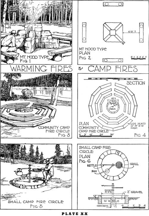
WARMING FIRES AND CAMP FIRES
THE Mount Hood type of warming fire (fig.1) is used in connection with swimming pools on forest campgrounds, and it provides a feature around which the bathers may sit to dry themselves after a plunge in cool waters. The temperature of the air among the large timber of some of the mountain forests is cool even during the many warm days of the summer months and these warming fires are a welcome feature. The splayed sides (fig. 2) provide a surface which reflects a maximum amount of heat.
There are three kinds of open fires: (a) The bonfire; (b) the campfire; (c) the open fireplace.
This part of the discussion is confined to the campfire, which may be for community-camp use or for individual groups of campers. The bonfire is a feature similar to the campfire, but larger, and usually for large groups.
The campfire is generally developed within a circular area which is well defined by a border of stones (preferably small boulders). This campfire may be for community groups or for single camp groups.
In the center of the campfire circle it is oftentimes desirable to construct an upright post of concrete or of iron against which the logs may rest, thus developing a more attractive fire than can be produced by laying the logs in horizontal position.
The small campfire circle (fig. 5) may also be used for cooking purposes, as shown in the sketch and in the accompanying plan (fig. 6).
|
|
PLATE XX. (click on image for a PDF version) |
| <<< Previous | <<< Contents>>> | Next >>> |
|
camp-stoves-fireplaces/sec6.htm Last Updated: 12-Sep-2011 |