|
Logging Railroads of the Lincoln National Forest, New Mexico
|

|
LOGGING RAILROAD TECHNOLOGY
The Nature of Logging Railroads
There are many influences affecting the physical plant of logging railroads. Perhaps the most significant is the size and quantity of the trees to be cut and transported. Another influential factor is the engineering practice of the connecting main line railroad. Yet another factor seems to be the accepted practices of the area, which are influenced by many things, including the background of the managers. All of these influences together result in typically distinctive logging railroads in a given timber region, and the logging railroads of the Lincoln National Forest were no exception.
In the early years the logging railroads were little more than extended sidings along the Alamogordo and Sacramento Mountain Railway main line to which logs were skidded for loading. The logging spurs tended to follow the more open valleys, both for ease of construction and for room to store logs prior to loading. As the logging moved further away from the A&SM line, the logging roads took on more of the character of the A&SM line itself. They matched its steep grades, its use of switchbacks and its very sharp curves. Curved timber trestles were notable for their numbers on the logging lines as well as on the A&SM line.
Civil Engineering
The A&SM line was built to a consistent set of engineering standards throughout its length. Its distinguishing feature was its many curves, practically all of them of 30 degrees or 193 foot radius. A seemingly endless series of such curves was utilized to wind the railroad around the mountain slopes while keeping to a constant gradient of something over five percent. Where the valley narrowed too much to permit even these sharp curves, as at Toboggan, a switchback was used to climb out of the canyon. In this way the consistent grade was kept as closely as possible. The short, very steep stretch just below Toboggan, said to be as much as 6-1/2 percent or 343 feet to the mile, proved to be the limiting or ruling grade for the entire line.
Railroad curvature is usually described in "degrees of curvature" meaning the interior angle subtended by a chord of 100 foot length along the curve. This comes from the practice of surveying railroads along the line of the route by offsets. The very sharp 30 degree (193 foot radius) curves of the A&SM compare with the typical 20 degree curves of the Denver & Rio Grande narrow gauge lines (288 foot radius) and the one to ten degree curves of most standard gauge railroads.
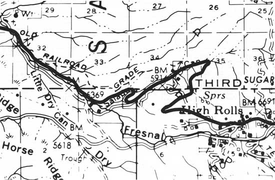
On an aerial photograph or large scale map, the A&SM stands out because of the extreme geometric precision of its features. The consistent radii of the curves and the perfection of its straight or "tangent" portions are characteristic of the engineering of railroads (Figure 34). Combined with gradients of about five percent, rarely exceeding six percent, these features distinguish the railroad lines from trails, roads and all but the most modern of paved highways.
|
| Figure 34. Alamogordo & Sacremento Mountain Railroad S-curves to gain elevation below High Rolls. The "old railroad grade" shown is in fact an old road. (click on image for a PDF version) |
The logging railroads exhibit all of the same characteristics. The chief difference between the A&SM and the logging railroads was in their conception of permanence. The A&SM was designed and built to last as long as possible. Culverts and water crossings were designed and built carefully to handle the necessary drainage, including cloud bursts and rapid snow melting. The entire roadbed was ditched for rapid drainage. The numerous timber trestles of the A&SM were built to standard designs allowing for ready replacement of individual timbers. The bridge decks were protected against fire with ballast or sheet metal. On the other hand, the typical logging railroad was intended to last only until the last tree rolled over the line. The subgrade could be less even and consistent. Provision for drainage, although necessary, could be less careful and certainly less permanent. Cross ties were usually untreated, with the intent they be used only once or, at most twice before they wore out. Customarily they were simply left behind when the rails were removed. Where the logging lines were longer lived, as with the line from Russia to Marcia which functioned for twenty years, the differences became fewer.
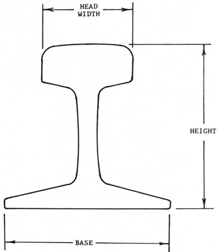
In terms of appearance, the logging lines were laid with lighter rail, poorer ties, and the rails were less well aligned. Whereas the A&SM track at its best appeared geometrically perfect with smooth sweeping curves, the logging spurs were uneven, inconsistent, and included many kinks and minor deviations. Curves were no sharper than those on the A&SM, for they were near the limits of most rolling stock in the first place (Figure 35).
|
| Figure 35. Typical rail section. Longitudinal and diagonal braces complete the trestle. |
In contrast to their often casual construction, the logging railroads were surveyed and carefully laid out to follow the contours of the land. Earthworks were minimized. Curves, especially when viewed in aerial photographs, appear precisely circular and the line of the straight tracks is quite precise in spite of the uneven track. A degree of care and consistency was required to assure the stability of heavy loads and a minimum of derailments, but this was not always achieved.
The A&SM was built with rail of 60 pounds per yard, commonly referred to as "sixty pound rail." The rails of the logging spurs were varied, having been purchased in odd lots over a period of years. The weights per yard varied from 45 pounds to 65 pounds. This was generally considered light rail, especially after the first few years (The Timberman). Table 1 lists rail dimensions.
Table 1. Standard Rail Weights and Dimensions
| Weight (pounds per yard) |
Height (inches) |
Base (inches) |
Head Width (inches) |
| 40 | 3-1/2 | 3-1/2 | 1-7/8 |
| 45 | 3-11/16 | 3-11/16 | 2 |
| 50 | 3-7/8 | 3-7/8 | 2-1/8 |
| 55 | 4-1/16 | 4-1/16 | 2-1/4 |
| 60 | 4-1/4 | 4-1/4 | 2-3/8 |
| 65 | 4-7/16 | 4-7/16 | 2-13/32 |
| 70 | 4-5/8 | 4-5/8 | 2-7/16 |
| 75 | 4-13/16 | 4-13/16 | 2-15/32 |
| 80 | 5 | 5 | 2-1/2 |
| 85 | 5-3/16 | 5-3/16 | 2-9/16 |
| (after Howson 1921:127) | |||
Rail was a major item of expense in building the logging railroads. It was generally picked up and reused as long as it remained reasonably straight and undamaged. Even when badly worn or kinked it could be sold for scrap at prime rates. Thus, it is rare to find more than odd lengths of rail left behind by a logging outfit. Spikes and rail joint bars or fishplates are distinctive items of track hardware, and are found more frequently along an abandoned track. It should be mentioned that rail is marked with lettering and numerals along the web which reveals the rolling mill, year of production, weight and cross section of the rail itself.
Cross ties were usually used untreated on the logging railroads. They were of the same dimensions as main line ties, typically 7" x 9" x 8', especially if tie cutting was done nearby. Culls and poorer quality ties were found on the logging lines because their life was to be short. Rails were often spiked directly to the ties without the benefit of tie plates to protect the timber. And it was not unusual to simply leave the ties in place when logging rails were picked up for use elsewhere. In fact, it is often possible to detect an old rail bed by the extra thick growth of grass and trees fed by the rotting ties.
Ballast supports the ties and distributes the weight of the trains along the roadbed. On main lines the ballast is a water resistant material such as crushed rock, cinders, or smelter slag. On branches and short lines, it was often simply packed earth. This was the case in the Sacramento Mountain area railroads (The Railroad Gazette 1902). "Dirt track" railroads, as they were called, were usually adequate in dry country, but they could be difficult to maintain and to use during wet seasons. In the early 1900s the A&SM and the Alamogordo Lumber Company had troubles with tracks sinking into the mud at the spring thaw. Only in later years was cinder ballast, with some stone, used on the A&SM line, and then only in the bad spots.
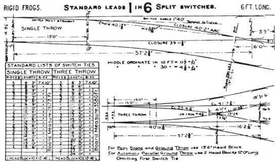
Track switches, or turnouts as they are called on the railroads, have a very distinctive geometric form. The accompanying figure illustrates standard designs of the type typical of logging railroads (Figure 36). The major parts of a turnout are the points and the frog. The points guide the wheels to one diverging track or the other, and there must be some mechanism to throw and lock them into place. The frog is the crossing of the diverging rails. Typically, turnouts are characterized by the frog number, which is a measure of the angle of divergence of the two tracks. That is, a number 9 frog diverges at an angle of approximately one in nine, and so forth. Other features of turnouts include the guard rails and their fittings, and one or two long heavy ties or "headblocks" which carry the point mechanism. Turnouts include many special parts of distinctive design as well as ordinary rail and fittings.
|
| Figure 36. Typical turnout design. |
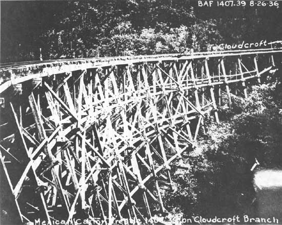
Because of the concentrated weights of rail equipment, water crossings on a railroad assumed highly characteristic forms. Culverts ranged from simple tie openings set just below the rails to very substantial box structures set deep in fills. Occasionally a chute over the tracks would be used to achieve drainage in deep cuts on sidehills. Timber trestles of framed or pile construction remain one of the distinguishing features of western railroads to this day. They were quick and cheap to build, although prodigal of timber (Figure 37).
|
| Figure 37. Detail of Mexican Canyon trestle, ca. 1936. (Southern Pacific photo) |
Trestles would often be built to open a railroad as quickly as possible, to be filled in later to reduce maintenance costs and provide a more stable roadbed. Such an evolution was all but universal in the southwest, but it occurred only to a very limited extant on the A&SM. The use of numerous and large timber trestles continued throughout the life of the railroad, adding greatly to its cost of upkeep and concurrently restricting the speeds of the trains.
A trestle structure is very much standardized to permit rapid construction and easy replacement of individual timbers. Repair timbers could be stock piled, and it was often possible to repair or replace a fire-damaged trestle in a matter of days. The basis of a trestle is a series of bents—vertical frames—precisely spaced at fourteen foot intervals. Each bent rests on a foundation or is made up of round piles driven into the ground. Each bent is capped with a cross timber. And the cap is then the foundation for either the deck carrying the track or another story of bents.
Trestle designs are adapted to the weight of trains passing over them. Light duty trestles have four pile bents. Five or six piles are used for heavier loadings. Similarly, the decks may be made up of as few as four stringers for the lightest loads with as many as eight stringers for heavier loading. Ties are laid on the stringers to support the rails. Bridge ties are deeper and longer than ordinary ties and are laid closer together. Often bridge decks and ties would be protected with galvanized sheet iron and ballast for fire protection (Figure 38). Hardworking steam locomotives often dropped hot cinders or dollops of fuel oil along the track causing small fires.

|
| Figure 38. Log train on the "S" trestle below Cloudcroft, ca. 1910, showing the complex mechanical detail of steam railroading. A layer of gravel is used to protect the ties and stringers from sparks. (By Bailey Pharmacy) |
Facilities
Locomotives and steam logging equipment required a lot of maintenance and adjustment to operate well. As long as the A&SM operated the owners kept a roundhouse and machine shop at Alamogordo to service the locomotives. Major overhauls and repairs were done at the large El Paso shops built by the EP&SW in 1906.
Locomotive fuel for the A&SM was stockpiled at Alamogordo. During 1899 wood was used, but this was soon replaced with coal from Capitan and Dawson. During 1911 one locomotive was converted to oil fuel, followed by the others over a span of years. With either coal or oil fuel, one tender load would be enough for a round trip to Russia (Howes 1965).
Water was available on the A&SM for locomotives at Alamogordo, Wooten and Cloudcroft. Wooten had a plant for the chemical treatment of locomotive water in addition to its wooden water tank (Southern Pacific Co. 1935).
Fuel for the logging railroads was brought up to the main camps, such as Marcia, in car load lots. Coal was shoveled by hand into locomotive tenders or loader bunkers. Oil could be handled with pumps or elevated tanks. Water was provided only at the main camps, but the logging locomotives were all equipped with steam pumps or siphons to draw water from any available source in the woods. Water tanks were known to exist at the camps at James Canyon, Marcia, Hay Canyon and Agua Chiquita Canyon.
Muddy water from ponds and stream beds contributed much to the cost of running the logging locomotives. Boiler washing was required much more often. The mud would cause hot spots in the boiler, and would plug the gauge glass used to measure the height or level of water in the boiler. The latter condition could and did deceive the engineman into believing he had more water in the boiler than he actually did. It is likely that conditions such as these caused the two disastrous explosions of logging locomotives in the Sacramento Mountains.
The main logging camps all had a "roundhouse," a crude engine shed where daily running repairs were made. A small but capable machine shop was an indispensible part of the facility. Most repairs to a logging locomotive or steam loader could be made in such a shop. Occasionally, however, logging locomotives would be sent down to Alamogordo and El Paso for major overhaul or boiler work. Car repairs were much simpler than locomotive work, and could be done in the logging camps or at Alamogordo as a matter of routine.
Shays, Heislers and Rod Lokeys
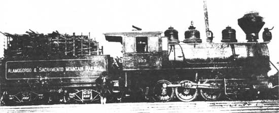
A modest but interesting collection of locomotives served in the Sacramento Mountains. More often than not they represented the typical and accepted practice of similar railroads across the country. The A&SM opened for business with two small locomotives, one a leftover from the Columbian Exposition where it had been exhibited by the Baldwin Locomotive Works. With only four drive wheels it quickly proved to be too small for regular service. It soon disappeared from the mountains. The second locomotive was an eight driver freight locomotive of a much more suitable design. The third and fourth locomotives were of the "consolidation" or 2-8-0 type, i.e., with a two-wheel lead truck and eight drivers (Figure 39). These proved to be quite satisfactory and set the style for the A&SM for the rest of its life (Howes 1965).
|
| Figure 39. Alamogordo & Sacramento Mountain Railway locomotive in its original wood burning condition with high woodracks and patented Radley-Hunter-spark-arresting smoke stack, ca. 1899. Soon afterward, coal fuel was used. This locomotive was further changed to burn oil fuel in 1914. (William Bissinger collection) |
From the beginning, the locomotives of the A&SM were specially equipped to cope with the steep grades and sharp curves. Drive wheels were low, ranging from 46 to 51 inches in diameter. On the eight-driver locomotives, flanges were omitted and tires widened on the four intermediate drivers. This theoretically reduced friction on the sharper curves, although in practice it also reduced tractive power. Later locomotives had all drivers flanged. The difference was made up with increased side play in the axle bearings. The A&SM locomotives all had longer than normal couplings between engine and tender. A useful piece of gear invented on the A&SM was a steam-jet rail washer invented by engineer Jim Riddle. The jets cleaned the rail ahead of the drivers, assuring a grease free surface and maximum tractive power (Neal 1966:42).
The A&SM made the headlines when in 1902 it took delivery of the largest Shay geared drive locomotive built to date. Obviously an attempt to increase the overall capacity of the railroad, the locomotive was a magnificent machine weighing 291,000 pounds in working order (The Railroad Gazette 1902). The Shay locomotive was a patented design built by the Lima Locomotive & Machine Company of Lima, Ohio. The boiler, cab, and tender were carried on four center-bearing swivel trucks.
A large three-cylinder double-action steam engine was mounted on the right side of the firebox driving a longitudinal crankshaft. The boiler was offset to the left of the locomotive centerline to balance the weight of the engine. Power was transmitted from the crankshaft to all four trucks via a longitudinal shaft system running low on the right side of the locomotive. Universals and slip joints accommodated curves and uneven track. Bevel gears transmitted power from the shafting to the drive wheels. Strange looking and lopsided to the uninitiated eye, Shay locomotives proved to be very effective on logging railroads in particular and some 2770 were built between 1879 and 1945 (Koch 1971). Starting in 1899, the Alamogordo Lumber Company began using three 65-ton, three-truck Shays. They were quite successful on the logging spurs, and there was plenty of opportunity to try them out on the A&SM main line (Koch 1971:400-401).
Although it was not a long-term success, the big Shay made several spectacular trips over the A&SM. One trip saw it pulling 27 empty log cars of 16,000 pounds each plus a caboose weighing 12,000 pounds, a net weight of 222 tons, all the way to Cox Canyon. On another well recorded trip, the locomotive pulled 41 empty log cars and the caboose, net 334 tons, to Toboggan (Figure 40). This train was too long to traverse the switchbacks (The Railroad Gazette 1902). It is likely that trains of this length also proved to be unstable on the numerous sharp curves. The downfall of the Shay locomotive in main line service on the A&SM was its slow speed, coupled with high maintenance costs on the complex drive train. The difficulty of lubricating the gears and universals on a long run added to the problem. The big Shay did not find a permanent home on the A&SM and was sold in a few years (Homes 1965).

|
| Figure 40. In early 1902, the brand new Shay patent geared locomotive, number 105, pulled a 334-ton train of 41 empty log cars from Alamogordo to Toboggan. The train was stopped for the photographer on the "S" curve between El Valle and Pinto. (Baldwin-Lima-Hamilton Corp. collection) |
The original four A&SM locomotives were supplemented with members of a class of four EP&NE locomotives purchased in 1900. Two or three of this group were outfitted for service on the A&SM, and they continued to perform long after the big Shay was gone. These locomotives were conventional if small freight locomotives of the same low-drivered 2-8-0 type. Even at this early date, the locomotives assigned to the A&SM were noticeably smaller than the locomotives going into service between El Paso and Tucumcari. The constraints of the sharp curves of the A&SM were already becoming apparent (Howes 1965).
Only two more locomotives were permanently assigned to the A&SM. These were a pair of 2-8-0 types obtained when the EP&SW purchased the Arizona & New Mexico Railway in 1921. Although larger than the other locomotives assigned to the A&SM, this pair was obsolete for other work in 1921. They found a home on the Cloudcroft line and remained in service until the end in 1947 (Howes 1965).
Various attempts were made to find more powerful locomotives for the A&SM. In 1916, the EP&SW purchased another four-truck Shay. This one was even heavier than the 1902 example, weighing in at over 150 tons. It was over a year being rebuilt at the El Paso shops, while roadbed improvements were made along the A&SM. It wasn't until January 1918 that trial runs were made, and they turned out to be dismal failures. The enormous locomotive proved to be too cumbersome for the sharp curves, and it demanded unreasonable quantities of fuel and water. On its last trip, it failed to reach Cloudcroft on a single tank of fuel (Weekly Cloudcrofter 1917c).
This was totally unacceptable as a long-term proposition, and the big locomotive was sold in 1920 to the Red River Lumber Company in California. It worked there for many years (Howes 1965).
In 1922 the EP&SW tried once more to introduce a larger locomotive to the Cloudcroft run. In this attempt, a freight locomotive—one of the older engines used for switching at Dawson—was brought to Alamogordo, coupled to a heavy train and headed out for Cloudcroft. The locomotive broke a total of eight rails, seven on the sharp curves above El Valle, before derailing completely. The curves had won again (Alamogordo News 1918).
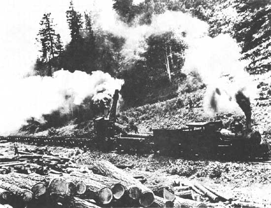
Over on the logging railroads, the Shay locomotive proved to be the master of its work. The three logging locomotives bought during 1899 were all 65 ton three-truck Shays. The boiler, engine, cab and fuel bunker were supported by two trucks, with the water tank perched on the third truck. With a relatively light axle loading and short wheelbase trucks, the Shays were very much at home on the woods spurs, and were often found on the main line as well. Additional Shays were purchased in 1902 and 1921 (Figure 41). The last one was similar to the first, weighing 70 tons, and with many modernized details of construction (Koch 1971:455). An ancient used Shay was also purchased in the 1920s (Figure 42).

|
| Figure 41. Southwest Lumber Company log train near Russia hauled by Shay locomotive number 1. June 27, 1928. (By E. S. Shipp. USDA Forest Service photo 233046) |
|
| Figure 42. Southwest Lumber Company loading logs in Water Canyon. Shay locomotive number 6. June 28, 1928. (By E. S. Shipp. USDA Forest Service photo 233024) |
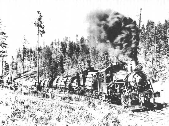
In 1927, needing more motive power, SWLCo purchased a Heisler gear drive locomotive. The Heisler was at this time a serious competitor of the Shay. The builder had developed an efficient design that was growing in popularity in the west. The Heisler design placed a two-cylinder V-engine beneath the locomotive boiler midway between the two flexible trucks of the locomotive. The V-engine drove a central shaft, with universal joints to transmit power to the trucks. The third truck supported the water tank. The Heisler had the advantage of a symmetrical design, with some easing of the stresses on the track. Its disadvantage was that servicing required a pit between the rails (Anon. 1982) (also see Spoerl 1981:44, fig. 1).
The Breece railroad used five locomotives during its short operating lifetime. Each was of a different type, and only one was purchased new from the builders. Breece started out with one old locomotive originally built for the A&SM and sold to CL&L to open their operation. An additional locomotive was a 70 ton, three-truck Heisler purchased in 1926, only months before SWLCo bought theirs (Figure 43). It was sold to SWLCo to replace their Heisler, which was destroyed in a boiler explosion (Anon. 1982:159, 161).
|
| Figure 43. George E. Breece Lumber Co. log train, pulled by Heisler locomotive 15, leaving landing on Mescalero Apache Reservation. June 30, 1928. (By E. S. Shipp. USDA Forest Service photo 233417) |
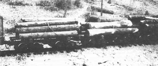
The backbone of the rolling stock fleet was the large group of log cars used to carry timber. During the early years, about 145 Russel skeleton frame cars were purchased by Alamogordo Lumber Company. Thirty five were delivered in December 1899, sixty in May 1900, and another fifty in late summer of 1900. A few such cars were apparently on the line when it opened in November 1898 (Alamogordo News 1899c, 1900b, 1900c). The log cars were small and light, weighing about 16,000 pounds each (Figure 44). They were about 22 feet long with 22 or 24 inch wheels, and were intended to carry 20 foot logs. The cars were equipped with Westinghouse automatic air brakes and hand brakes. By 1907, the ownership of the log cars had passed to the EP&SW and about 150 were in use (Official Railway Equipment Register 1907).
|
| Figure 44. Loads of twenty foot logs on the Alamogordo & Sacramento Mountain Railway, ca. 1903-1905. (By Royal A Prentice. Museum of New Mexico) |
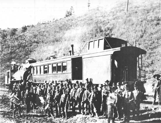
The A&SM owned four cabooses; three were short cars with side doors and cupolas. They could accommodate three or four passengers along with the train crew. The fourth caboose was something of a showpiece with a long well-varnished body and gold leaf lettering (Figure 45). The car included accommodation for the train crew in a cupola, a good number of seated passengers in one end, and baggage, express and the U.S. Mail at the other end. The passenger end of the car sported an elaborate brass railing.
|
| Figure 45. Dedication Day of the A&SM, celebrated at Toboggan on November 16, 1898. The elegant car combined the functions of passenger coach, baggage-mail-express car, and caboose in one vehicle, a necessity on the steeply graded railroad. (By Bushong & Feldman. Museum of New Mexico photo 14914) |
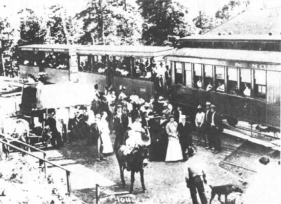
The new resort at Cloudcroft resulted in a sudden explosion of passenger traffic which was carried in four open-sided excursion coaches hurriedly converted from flat cars. Longitudinal wooden benches and canvas curtains for the open sides were the only amenities offered (Official Railway Equipment Register). It was not until the EP&SW had operated the railroad for some time that true passenger cars were operated on the A&SM line. At least two cars—a combination baggage-coach and a full coach—were equipped with short wheelbase trucks and wide-swing couplers to enable them to get around the sharp curves (Alamogordo News 1907a) (Figure 46).
|
| Figure 46. An excursion train ready to leave Cloudcroft, ca. 1909. Although the line had been owned by the EP&SW for several years, the open-sided cars remained lettered for the A&SM. (Orris Smith collection) |
Ordinary freight cars could easily traverse the A&SM line, provided they were not too long. As the years passed and freight cars grew in length, the SP found it necessary to place some restrictions on the cars permitted on the branch. The restrictions, published in the employees' timetables, prohibited cars over 42 feet length and over 14 ft. 6 in. height. Lateral play in the couplers was required to be over 2 inches either side of center (Southern Pacific Co. 1935).
About 200 larger log cars were brought in by the SP during the boom years of logging in the late 1920s. Similar to the Russel cars, these cars were larger and heavier, with regular 33 inch wheels. Car length was about 24 feet. An important feature of these cars was the retaining brake system. This added a controlled or direct straight air brake to the universal Westinghouse automatic air brake. A second brake line with hoses coupled between the cars was used to control the added brake. This added much to the reliability and safety of operations on the A&SM (Neal 1966:63).
Locomotive Rosters (Tables 2, 3, 4. 5)
The following locomotive rosters are in an abbreviated form, which may best be explained by the following example:
101 2-8-2T Baldwin #16103, 8/1898 46-21x24-135000
101 is the road number, i.e., the number assigned to the locomotive by the operating company, and usually found painted on the locomotive in one or more places.
2-8-2T represents the locomotive wheel arrangement in the Whyte System (Bruce 1952:19, 25). The first digit counts the pilot truck wheels. The second digit counts the driving wheels. The third digit counts the trailing wheels. Zero is used to indicate none. "T" means a tank locomotive carrying its fuel and water on the locomotive itself rather than in a separate tender. Gear drive locomotives are indicated by 3T Shay or 3T Heisler, indicating the number of driving trucks plus the maker of the locomotive.
Baldwin #16103, 8/1898 is the builder, builder's serial number, and date built (month/year). The builder's serial number is found on cast plates, usually attached to the locomotive smokebox, and is often stamped into other parts of the locomotive. The builders of concern here are the Baldwin Locomotive Works, Philadelphia, Pennsylvania; Lima Locomotive and Machine Company, Lima, Ohio; Heisler Locomotive Works, Erie, Pennsylvania; H. K. Porter Company, Pittsburgh, Pennsylvania; and Schenectady Locomotive Works, Schenectaday, New York.
46-21x24-135000 gives key locomotive dimensions:
46 is the driving wheel diameter in inches
21x24 is the diameter and stroke of cylinders in inches
135000 is the total engine weight in pounds.
Table 2. Locomotives of the Alamogordo & Sacramento Mountain Railway
| Numbers | Descriptions | |||||||||
| 101 | 2-8-2T | Baldwin #16103, | 8/1898 | 46-21x24-135000 | ||||||
| 102 | 2-4-2T | Baldwin #13361, | 3/1893 | 44-14x24-72130 | ||||||
| 103 | 2-8-0 | Baldwin #16494, | 3/1899 | 46-21x24-140600 | ||||||
| 104 | 2-8-0 | Baldwin #17107, | 11/1899 | 46-21x24-140600 | ||||||
| 105 | 4T Shay | Lima #673, | 3/1902 | 40-(3)15x17-260300 | ||||||
| ||||||||||
Table 3. El Paso & Northeastern Railroad El Paso & Southwestern Railroad Southern Pacific Company
| EP&NE | EP&SW | SP | Descriptions | |||||||||
| 52 | 181 | 2505 | 2-8-0 | Baldwin #17397, | 3/1900 | 50-21X26-141000 | ||||||
| 53 | 182 | 2506 | 2-8-0 | Baldwin #17398, | 3/1900 | 50-21x26-141000 | ||||||
| 54 | 183 | 2507 | 2-8-0 | Baldwin #17443, | 3/1900 | 50-21x26-141000 | ||||||
| 55 | 184 | 2508 | 2-8-0 | Baldwin #17444, | 3/1900 | 50-21x26-141000 | ||||||
| — | 99 | — | 4T Shay | Lima #1893, | 8/1907 | 46-(3)17x18-213700 | ||||||
| A&NM | EP&SW | SP | Descriptions | |||||||||
| 19 | 217 | 2510 | 2-8-0 | Baldwin #20237, | 3/1902 | 51-21 1/2x28-176000 | ||||||
| 24 | 218 | 2511 | 2-8-0 | Baldwin #26656, | 10/1905 | 51-21 1/2x28-176000 | ||||||
| ||||||||||||
Table 4. Logging Locomotives of the Alamogordo Lumber Company, 1898-1916: Sacramento Mountain Lumber Company, 1916-1920: and Southwest Lumber Company. 1920-1945
| Road ALCo | Numbers SMLCo |
SWLCo | Descriptions | ||||||||
| 2 | 2 | 2 | 3T Shay Lima #568, | 3/1899 | 33-(3)14x14-128200# light | ||||||
| 3 | 3 | 3 | 3T Shay Lima #580, | 9/1899 | 33-(3)14x14 | ||||||
| 4 | — | — | 3T Shay Lima #587, | 11/1899 | 33-(3)14x14 | ||||||
| 5 | 5 | 5 | 3T Shay Lima #700, | 6/1902 | 36-(3)14x14-137200# light | ||||||
| — | — | 1 | 3T Shay Lima #3155, | 6/1921 | 36-(3)12x15 | ||||||
| — | — | 6 | 3T Shay Lima #483, | 3/1895 | 32-(3)12x12-86200# light | ||||||
| — | — | 3 | 3T Heisler Heisler #1540, | 2/1927 | 70 ton | ||||||
| — | — | 15 | 3T Heisler Heisler #1534, | 1926 | 70 ton | ||||||
| |||||||||||
Table 5. Logging Locomotives of the Cloudcroft Lumber and Land Company, 1924-1926 and George E. Breece Lumber Company, 1926-1940
| Road Number | Descriptions | |||||||||
| 1 | 2-8-0 | Baldwin #16494, | 2/1899 | 46-21x24-140600 | ||||||
| 3 | 2T Shay | Lima #2611, | 1/1913 | 36-(3)10x10 | ||||||
| 6 | 2-6-2T | Porter #6727, | 8/1922 | 44-19x24 | ||||||
| 15 | 3T Heisler | Heisler #1534, | 1926 | 70 ton, 3 truck | ||||||
| 102 | 2-6-2 | Schenectady #5526, | 8/1900 | 51-19x24-132000 | ||||||
| ||||||||||
| <<< Previous | <<< Contents>>> | Next >>> |
lincoln/cultres4/sec3.htm
Last Updated: 02-Sep-2008