|
CCC Forestry
|
|
Chapter XII
FOREST ENGINEERING
|
ENGINEERING plays an important role in forest administration. From the beginning of forest development work, land purchase or acquisition, the services of men trained in engineering are necessary. Surveys, roads and trails, bridges, water developments, logging plans, towers, telephone lines, radio communications, and the developments in forests for recreational use—all require engineering knowledge. Forest engineering is a combination of many engineering branches. As forestry develops and more complete and abundant use of forest values becomes more universal, additional types of engineering operations will be adapted to forest administration. Handbooks of the United States Forest Service and the various State services comprise a large library of forest engineering. In this chapter is contained a brief summary of the fundamentals of engineering as they apply to making surveys and constructing roads and trails, bridges, communication facilities, and lookout towers. |
Why Is Forest Engineering Necessary? A Summary of Engineering. | |||||
|
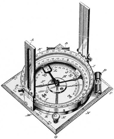
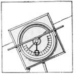
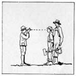
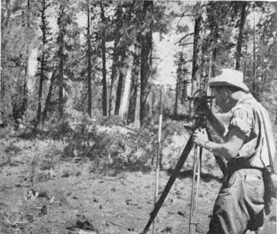
THE COMPASS Most forest surveys are made with the Forest Service compass, an instrument that resembles the simple box compass sold in 10-cent stores, and which may be compared with the mariner's compass used on ships.
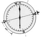
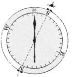
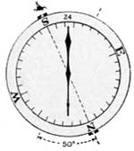
The Forest Service compass consists of two main parts: (1) A magnetized steel needle, swinging freely, but always pointing to the north magnetic pole; and (2) a pair of sights to enable the surveyor to determine an accurate line across the compass to a given distant point. The compass circle is divided into 360 degrees or parts; and the four quadrants or quarters of the circle (1/4 of 360 degrees equals 90 degrees) are marked North, South, East, and West. North and South are indicated by zero (0) and the letters "N" and "S", and from these points, in both directions, the degrees are numbered up to 90 (the positions of East, "E", and West, "W"). On an ordinary compass the positions of the four cardinal points run in clockwise succession—North, East, South, and West—but on the Forest Service compass the positions of East and West are reversed, so that clockwise they read North, West, South, and East. This reversal is made to facilitate reading the bearing (the direction from the compass to any point). Although readings are taken from the North end of the needle, the direction obtained is that of a line of sight from the observer to the point in question. Hence a true reading is obtained only by reversing the natural positions of East and West. A pair of spirit bubbles attached to the apron surrounding the compass plate aid in leveling the instrument. A lock screw on the base of the instrument may be tightened when the compass is not being used. This prevents wearing of the pivot, upon which the needle rests.
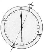
USING THE COMPASS To establish a line to form a given angle with another line, the readings must be determined beforehand. For instance, if a line is to form an angle of 50° with another given line, the compass is set up at the point on the given line from which the angle is to be turned. Suppose, for example, that a reading is taken along this given line and found to be South 26 West. To offset an angle of 50° to the West, the compass is turned 50° to a position where the needle reads South 76 West (26° ± 50°), and a stake is driven at a point along the line of sight. If, instead of a point 50° to the West, a point 50° to the East of the South 26 West or given line is desired, the compass is set up as before at the point on the given line from which the angle is to be turned, and a sight (South 26 West) is taken along this given line (to reestablish the base line). The compass is then turned 50° to the East to a point where it reads South 24 East (26° from S 26 W to S plus 24° to S 24 E, equals 50°), and the stake is set along that line.
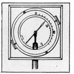
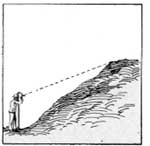
The Forest Service compass has an attachment that serves as a clinometer, or instrument to measure angles of elevation. It is possible, for instance, to measure the angle formed by a line from the observer to the base of a tree and a similar line from the observer to the top of the tree, or to measure the slope of a hill. The clinometer consists of a free swinging bar attached to the pivot below the needle. When the compass is tipped edgewise to a vertical position this bar swings pendulum-fashion and comes to rest pointing straight down. Just as a plumb bob points downward regardless of the angle of its support, so the bar maintains a vertical position regardless of the position of the sights and compass plate. When the sights are absolutely level, the pointer on the bar coincides with the zero position on the plate floor. However, if the compassman is sighting at the top of a tree, the front sight is higher than the rear sight—the scale moves forward and upward as the instrument is tilted upward, but the plumb bar remains vertically suspended so that it coincides with an angular mark on the scale. When the instrument is tilted to sight downhill the scale moves rearward, and the plumb bar rests at an angular reading on the other half of the scale. Slopes of distant hills may be read by tipping the instrument edgewise to face the observer a straight edge is laid across the sighting bar, and the instrument turned up or down on the swivel so that the straight edge parallels the edge of the distant slope. Angles are read on the clinometer scale as before.
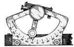
Like the clinometer on the compass, the Abney level is used to measure angles of elevation. It is based upon a spirit level and a graduated scale mounted on a sighting tube. The sighting tube fitted at one end with an eye piece through which the user looks to the other end where a horizontal hair line, or wire, cuts the field of view in two. The hair line and the peep sight, or eye correspond to the sights on the compass. Rigidly attached to the tube is a scale similar to the degree scale on the compass clinometer. A pointer, pivoted above the scale so that its point may be moved, along the scale, has a small spirit level fixed to it. When the sights are level and the spirit bubble centered, the pointer indicates zero on the scale. When the user sights with the instrument at an object that is not level with his eye, the bubble moves away from the center. Holding this sight, the operator tilts the spirit level until the bubble is centered. By tilting the spirit level, he also swings the pointer bar to an angular reading on the scale. This reading is the angle formed by the line of sight and the horizontal plane of the spirit level, or the angle of elevation of the object at which the instrument is being sighted. To facilitate alining the bubble, at the same time that the operator sights at his objective, a mirror has been set in the sighting tube to reflect the image of the bubble. Scales on the Abney level may be graduated in degrees, as on the compass clinometer, or in percent, to indicate the amount of rise or fall in 100 feet of horizontal distance, or in topographic units to indicate the rise or fall in 66 feet (66 feet is the common length of the surveyor's chain). Degree of slope may be changed to percent of slope by multiplying the tangent of the degree by 100. Tangent tables are included in most engineers' handbooks; they express the relationship between the length of the horizontal and vertical legs of any right-angled triangle. For instance, the tangent of 30° is .5774 (found in the table) and the slope is 57.74 percent (.5774 X 100); the tangent of 45° is 1, and the percent of slope, 100. To change percent to degrees, the process is reversed. If the grade percent is 10.5, that figure divided by 100 gives .105; and the nearest tangent number in the table is .10510 the tangent of 6° Distant slopes may be measured with the Abney by holding the sighting tube parallel with the slope (just as is done when distant slope readings are taken with the compass clinometer), and with the instrument in this position the bubble is leveled, thus moving the pointing bar to the angle of the slope. In using the Abney level one should always remember that the instrument is held at the height of the user's eye. To obtain a true reading of ground slopes, the line of sight should be to a height above the ground equal to the height of the instrument. A rod with the height of instrument marked on it may be held at the desired point by an assistant, or some feature of the assistant should be used as a target. (For information on height measurement of trees, etc., see chapter on Forest Mensuration, pp. 170-171.) When a given grade is to be established, as on a road or trail, the pointer bar may be set at the desired reading. Then by centering the leveling bubble by sighting up or down, the surveyor may direct the placing of stakes. In this manner trails in mountainous country may be located at the rate of one or two miles per hour. |
Measuring Vertical Angles.
Zero Reading. Reading the Angles. Alining the Bubble.
| |||||
|
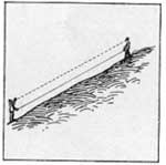
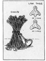
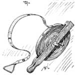
CHAINS AND TAPES In forest surveying a "chain" may be either a unit of distance (66 feet) or an instrument for measuring distance. The chain, as a unit of length, facilitates the measurement of acreage—a strip 10 chains (660 feet) long, and 1 chain wide equals 1 acre. In measuring distance, 80 chains equal 1 mile. The instrument known as the chain is composed of 100 links, each 0.66 foot in length. The 66-foot chain is often too long for woods work, and a shorter one of 33 feet, or 50 links is used. Every tenth link on the chain is fitted with a brass tag on the edge of which are indentations or teeth to indicate its position. The first tag has one tooth, the second, two, etc. A handle, one link long, is attached to each end of the chain, so that a 66-foot chain has 98 links and 2 one link handles. Steel tapes also are used for measuring distances. They are lighter and less bulky than chains, but are more likely to break with rough usage. Often they are of the same length as chains (66 or 33 feet) and marked at each link length. Commonly, however, two-chain tapes (132 feet) or five-chain tapes (330 feet) are used. Other tapes may be 100 feet or 50 feet long, graduated in inches or tenths of feet. In practice, it is common to call the instrument of measurement (whether tape or chain) a chain. MAKING CHAIN MEASUREMENT Two men usually are employed to make chain measurements. To mark and tally distances, 11 pins are used. These pins are made of heavy iron or steel wire, about one-eighth to one-fourth inch thick and 15 inches long, pointed at one end and bent into a ring at the other. Strips of white or red cloth are sometimes tied to the rings to aid in finding the pins in underbrush. In chaining distances, one pin is placed at the starting point and the front chainman, retaining 10 pins, measures off one chain length and marks his position with the first chain pin. The rear chainman then picks up the starting pin and goes forward to this first chain pin, while the front man drags the chain another length to set the second chain pin. By this procedure 10 chains may be measured without stopping to tally each one. When the tenth chain has been measured, the rear man has 10 pins in his possession. The eleventh pin marks the final point. If the end of the line has been reached before the front man's 10 pins have been played out, the rear man's collection of pins indicates the chained length. Fractions of chains are read from the chain itself, the link tags marking links in multiples of 10. On level ground the chain may be stretched along the surface, but in hilly country it must be kept level by raising the downhill end and lowering the uphill end. When hills are very steep it is often necessary to "break chain," or measure in half chain lengths in order to get the true horizontal distance. Short chains (33 feet), one-half the length of a regular chain, may be used to advantage. Slope chains are often used to enable chainmen to measure along the slope instead of breaking chain. These chains usually are 2-1/2 chains long, the first two chain lengths being standard (132 feet) and the extra length ("trailer") graduated to offset the influence of the slope. With an Abney level fitted with a topographic scale a slope reading is taken. The reading on the topographic scale shows the difference in elevation between the two points measured. On the trailer are marks corresponding to the reading of the topographic scale. Thus, a chain stretched 132 feet along a slope that rises 38 feet in one chain must be extended 20.42 feet to give the true horizontal distance of two chains. When the man using the Abney reads a 38-foot rise on the topographic scale, the chainmen extend the trailer to a point marked "38" (20.42 feet from the end of the two-chain mark).
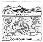
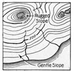
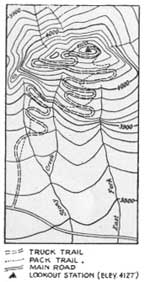
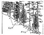
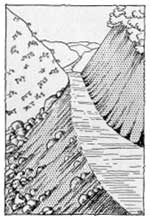
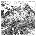
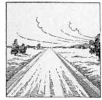
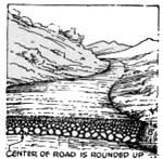
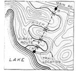
To make plans for any forest engineering project maps are necessary. For almost all areas in the United States some sort of maps are available. Often, however, these maps must be checked or details not included in the original survey must be added. Compass and chain mapping, with Abney readings for slopes and elevations, is adequate for most forest surveys. When topographic maps are available, trails can be located on these maps before field observations are made. Topographic maps show the differences in elevation, at regular intervals, by means of contour lines. These lines are drawn connecting points of a given elevation. If, for instance, contour lines (lines, all points on which are at the same elevation above sea level) of 20-foot intervals were actually drawn on the surface of a section of hilly land, one would cross four lines in walking from a 100-foot elevation to a point 200 feet high. On uneven ground, starting at the 100-foot contour line and walking uphill one would cross the 120-foot line, then the 140-foot line; and if he then descended into a hollow, he would recross the 120-foot line and possibly the 100-foot line before ascending the other side of the hollow to recross the 120-foot line. The position of contour lines may be indicated by imagining a section of land in a huge tank of water, with the water just at sea level. If the water is raised to a depth of 20 feet, a new water line (contour line) appears; all the land higher than 20 feet is above the water, and all less than 20 feet is submerged. As the water is raised in 20-foot levels, new contour lines appear. Looking straight down, as on a map, the lines on steep slopes appear close together, and on gentle slopes, farther apart. The United States Geological Survey has made topographic maps of large areas, and the areas not already mapped are in process of survey. On maps of rugged country, the contour intervals are 50 feet or even 100 feet apart, but in flatter areas 10- or 5-foot intervals are used. The spacing of the lines on a map indicate the topography of the country. A comparatively level stretch will be indicated with contour lines far apart; a steep mountain with crowded lines; and a gentle slope with contour spacing somewhere between that for level and rugged land. To lay out a trail on a topographic map one must know the contour interval (distance between contour lines) and the map scale. These are marked on the map legend. To locate a trail, as for instance from a road intersection to a tower on a ridge, divide the allowable grade into the contour interval to obtain the least number of feet of horizontal distance permissible between contour changes. For example, if the allowable grade is 10 percent and the contour interval is 20 feet, then, according to the rule, it is necessary to divide 0.10 into 20 which gives 200, the least horizontal distance permissible between contour lines. By the same principle a map with a scale of 400 feet to the inch would show a trail of at least one-half inch (200 feet) between contour lines. If the scale were 800 feet to the inch, the trail line would run at least one-quarter inch between contours. When the figure for the trail has thus been obtained it may then be sketched on the map. When a number of trails are sketched, the shortest or most adequate one may be chosen for construction. Contour maps may be used also in estimating the area of land to be flooded by a dam or stream change, and the necessary cuts and fills in trail construction. |
Use of Pins.
Watch the Pins!
Slope Chains. What is a Trailer? How to Measure Slopes. Providing Details for Maps. Use of "Topo" Maps. What Are Contour Lines?
A Section of Land in a Tank of Water. Look Straight Down.
How to Lay Out a Trail With Contour Map.
Another Use for "Topo" Maps. | |||||
|
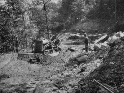
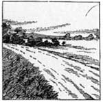
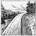
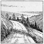
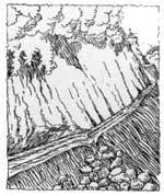
TRUCK TRAILS To obtain the maximum use from forests, and to give them adequate protection against fire, it is necessary to provide means of access for men and machinery. Truck trails and other trails permit the development of areas that were formerly in accessible and facilitate transportation of men and equipment.
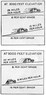
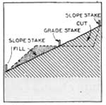
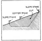
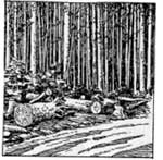
Three classes of truck trails are recognized by the United States Forest Service. This classification has been adopted by some States and has been used as standard for Emergency Conservation Work projects. Low Service truck trails are constructed where speeds up to 15 miles per hour are enough for all activities, such as on little used roads to lookout and guard stations, and short spur roads into camps. Medium Service truck trails are adequate where a speed of 16 to 25 miles per hour is desirable. They are used where low service roads are inadequate such as for connecting headquarters and ranger stations, for areas of high fire hazard, for long hauls of timber, products, fire fighters or livestock, and to serve popular recreational areas and small towns. High Service truck trails will permit speeds exceeding 25 miles per hour, and are important as main travel routes for protection and administration, or for through travel. TRUCK TRAIL LOCATION In laying out a truck trail or other type of trail there are a number of elements to be considered. (1) Purposes: Truck trails should be so located and constructed as to serve all forest needs. If a truck trail is to be used for timber operations, it should be made accessible to timber sale areas; if for protection, it should provide for getting personnel into hazardous areas and possibly serve also as a fire break; if for recreation, it should reach into sites of recreational value. All these uses should be considered before finally deciding upon the location for a truck trail. (2) Esthetic value: Road beautification should he considered in planning the project. Even if the truck trail is not intended primarily for recreational or tourist travel, it may eventually be used for such purpose. Although picturesque truck trails may have no greater utility than ugly ones, care should be given to esthetic values. Particular attention should be given to roadside cleanup, such as the disposal of timber and debris incident to construction. (3) Grade: Maximum grades have been established for the various truck trail classes and for various elevations. A car or truck loses 3-1/2 percent of its power with each 1,000 feet rise in elevation. For a low service truck trail at 3,000 feet above sea level, therefore, the maximum grade is 15 percent but at 9,000 feet, 11 percent is maximum. Since most modern motor vehicles can climb steep grades, it is often possible to reduce construction costs by increasing the grade. A much shorter truck trail may be built if a few steep grades are included instead of winding the location around hills. Grades steep enough to cause excessive erosion and rutting should not be permitted. The purpose of the truck trail will govern the allowable grade. Heavy logging trucks, for instance, may not be able to negotiate steep hills. Speed is reduced on any up-hill grade, and it is often necessary to travel down hill at slow speeds. Grades that shorten the route but require greater traveling time ordinarily are to be avoided. (4) Alinement: Truck trails should be located with as few sharp curves as possible, considering allowable cost. Straight stretches or long sweeping curves do not slow up travel as do short turns, nor are they as dangerous. On side-hill location it is often practicable to eliminate short curves by cutting or filling. (5) Width: Truck trails are usually constructed of single-track width. Where the amount of traffic justifies it, a double-track width may be used. Wide roads necessitate greater cuts and fills than do narrow ones. On steep side hills construction costs increase tremendously with the width of road. (6) Type of soil: The difficulties and expense of construction are influenced largely by the type of soil through which a truck trail passes. Spongy and boggy ground or soil types subject to heavy erosion should be avoided. It is more difficult to secure drainage on clays than on sands or rocks, but loose sands and rocks should be avoided in side-hill locations. (7) Clearing: Unimportant truck trails may be shifted higher or lower on slopes to avoid large trees and clumps of trees that involve excessive clearing. On level lands such sites may be avoided by long curves that will not add to road costs. Medium service and high service truck trails should ordinarily not be shifted much to avoid clearing, unless this can be done without affecting the service value of the trail. (8) Excavation: Cuts and fills increase initial cost and often make maintenance expensive. Alinement and speed requirements will determine the amount of excavation and fill. Where possible, excavated material should be used for fills. (9) Drainage: To a great extent the life of any road depends upon drainage conditions. Advantage should be taken of natural drainage. Level roads require more drainage than do roads with reasonable gradient. Adequate drainage should always he provided. (10) Bridges: Before bridges are planned for any road or trail their necessity should be definitely determined. Often it is possible to avoid stream crossings or to reduce the number of crossings by following one side of the stream. When all other conditions are equal, roads with bridges cost more to build and to maintain than do roads without them; hence, the road engineer should weigh carefully the cost and utility of a number of possible routes before his final decision is reached. When bridges are necessary, either a straight stretch or a long curve should constitute the approach. Knowledge of high- and low-water levels, stream-bank conditions, and possibilities of good foundation will aid in bridge location. The course of unimportant shallow streams may be changed in some instances, to decrease bridge building. (11) Ownership of land: When private land must be traversed, sufficient right-of-way should be obtained to enable future improvements to be made without entailing more problems of ownership. Scanty right-of-way may not allow width for future enlargement or permit enough trees to remain, if private owners start cutting, to add esthetic value to the truck trail. SURVEYS Before construction work starts on a forest truck trail, a location survey is necessary. The use of the truck trail and possible improvements such as greater width and better alinement for future needs should be considered. For most forest purposes, surveys with Abney level, compass, and tape are adequate. All curves, cuts, and fills should be located on the map, and the necessary construction work involved should be computed so that it may be compared with that of alternate routes. When the route has been definitely determined, it is staked out with center stakes or grade stakes, ordinarily placed at 100-foot intervals. On curves and over rough topography, center stakes may be set closer than 100 feet if necessary. Slope stakes, in addition to center stakes are needed: (a) To indicate how far to cut into a bank, (b) to guide workers in making cuts, blasting, and clearing, and (c) to mark the "toes" or lower edges of fills, and to indicate height of fill. Slope stakes are set opposite center line stakes, at right angles to the road line. CONSTRUCTION There are four major activities in forest road construction: (a) Clearing, (b) excavation, (C) drainage, (d) finishing. CLEARING Removal of trees should be limited to those on the proposed truck trail site, and those injured in construction. Trees on steep slopes, whose main roots have been cut, and other dead or dying trees that may fall across the truck trail should be removed. Stumps allowed to remain should be at least one foot below the finished road. All others should be blasted or pulled. Where snow is likely to remain on the truck trail, wider clearings may be made to permit the entrance of sunlight. Such clearing is done on the sunny side, and only when the cost of clearing and the timber value are less than that of surfacing or drainage. On curves, thinning and pruning may be necessary to increase visibility. Large groups of trees, however, should not be removed for this purpose. Where the truck trail passes through cleared areas, a screen of trees on both sides may be planted to keep snow from drifting on to the truck trail. Brush disposal should be provided for, where much clearing is necessary. This may mean that clearing must be done a season in advance of the rest of the construction job. Brush, particularly along trails which will be open to public use, should be burned or carried out of sight into the woods. Stumps likewise should be removed from the trail side. The sawing and chopping gangs should work in advance of the tractors and trail builders, or "bulldozers." Large logs, if cut into lengths of 16 feet or less, may be pushed aside with the trail builder. Small trees and brush need not be cut if it is possible for tractors and trail builders to push them over. Larger trees may be pulled with tractors and cables. It is often possible for trail builders to undermine stumps on side hills by gouging out the slope beneath them. Some trees may be blasted out more economically than they can be cut or pulled, and it is often necessary to blast stumps. In most cases it is better to split or loosen a stump with dynamite, so that it can be removed with a tractor or trail builder, than to attempt to blast it out of the ground. Use should be found for the timber that is cut, rather than to allow it to remain along the right-of-way. Shelter and cover for wildlife should be considered in roadside cleanup. Small patches of brush which do not constitute fire hazards but which add to roadside beauty and form game shelter should be permitted to remain. EXCAVATION When large quantities of rock must be moved, plans should be made beforehand, and the most economical method chosen. Trail builders, tractors, rippers, and other mechanical devices should be used, when possible, to loosen rock or to move it after it has been blasted loose. Under many conditions, the use of dynamite or blasting powder is necessary to remove large rocks or to open up frozen soil. In all cases, blasting operations should be sufficiently in advance of succeeding construction that it will not conflict. with or hold up progress. Only experienced, qualified men should be permitted to place and discharge powder or dynamite. Experience in handling explosives is necessary to obtain safe and efficient use. The amount of powder or dynamite and the number of shots to be used will be determined by the amount and character of the rock excavations. If too little dynamite is used, expenses are increased through the necessity of reloading and refining. On the other hand, too liberal use of explosives is a wasteful process that should be avoided. Material that can be used for fills, or that will stick to the slope on the lower side of the road should be loosened but not blasted out of reach. When rocks and boulders have been sufficiently reduced by blasting, the trail builder or bulldozer is usually the most efficient machine for moving them from the road. With the blade at an angle facing the lower side of the slope, the trail builder is capable of pushing large rocks over the side. It is often possible to use the trail builder to direct the rock into holes and hollows and to build the lower side up to grade. Tractors with hoists or chains are sometimes necessary when the job is too big for the trail builder.
For side-hill excavation, the trail builder should be used only to open a way for the tractor and grader. It constructs a rough road over which a tractor-drawn grader may work to obtain the desired width and grade. On most truck trail projects, the ripper precedes the grader. The ripper, or scarifier is a machine fitted with heavy steel teeth that dig up the ground, loosening it so the grader can spread it out or scrape it off to grade. Through cuts often may have to be dug with picks and shovels, or blasted out, if much rock is encountered. The material taken from cuts should be used for nearby fills. Although the persistent rapidity of motion of the bulldozer or trail builder may seem at first to make it superior to the tractor and grader as a dirt mover, dirt can actually be moved cheaper with the tractor and grader where they can be used. The grader should always be used as soon as the trail builder has roughed out a sufficient trail. A finished job requires the use of the grader. Banks which are not excessively rocky may be gouged out with the grader, while the bulldozer goes ahead to tackle the harder jobs. When not employed in opening up a trail for the grader, the bulldozer may be used to make fills or to pare off the tops of small humps and ridges. Fills may be made by end-haul or from borrow pits. End-hauling consists of removing earth from the higher spots near the fill and depositing it in the low spots. When earth and small rock must be end-hauled more than 100 feet to fills, the tractor-scraper is more efficient than the bulldozer. Borrow pits are areas along the side of the road from which earth is taken to fill the low spots. Large borrow pits are ugly features and should be located out of sight of the truck trail whenever possible. Small borrow pits should be dug in places where extra width is desired. Roots and rocks should be removed from the truck trail to provide an evenly weaning surface that can be maintained by tractor and grader. Root and rock removal is usually done by a crew following the grader.
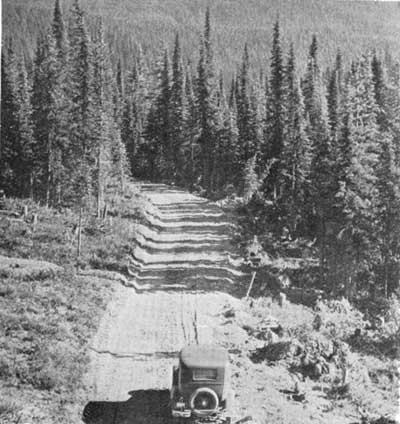
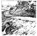
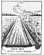
Proper drainage will reduce maintenance costs, prolong the life, and increase the efficiency of the truck trail. Three types of drainage are common to all roads: (a) Surface drainage, (b) cross drainage, (c) subsurface drainage. Surface drainage: Surface drainage is the disposition of water from the surface of the trail. Water, permitted to lie on the truck trail or to move over its surface, induces ruts and natural water channels which cause excessive erosion and make poor traveling conditions. This problem may be handled by: (1) Out-slope, (2) grade breaks, (3) dips, (4) in-slope and cross drains, (5) open-top culverts, (6) intercepting ditches, and (7) water bars. Out-slope: Where trail material will not become slippery in wet weather, and where small quantities of water may flow over the shoulder without wearing away the lower bank, out-sloping will provide surface drainage. A slope of one-fourth to one-half inch per foot of width is sufficient for most truck trail projects (a 12-foot road would be from 3 to 6 inches higher on the inside edge than on the outside). Grade breaks: To prevent run-off from attaining destructive speed and accumulating volume on long grades, the slope may be broken into short level sections or slight upgrades. Grade breaks should be made where the truck trail can be out-sloped to act as a spillway. Dips: Dips of not less than 30 feet in length may be installed to take care of excess run-off. These, like grade breaks, should be out-sloped and placed at points where erosion will not result. In-slopes and cross drains: Truck-trail surfaces which become slippery when wet or fill banks which erode rapidly are poor sites for out-sloped drainage. In such cases in-sloping may be used to direct run-off to the inside ditches. In-sloping usually requires culvert construction to conduct the water under the trail to the lower side. Because of this added expense, in-sloping is not used where other methods prove adequate. Open-top culverts: Open-top culverts may be constructed on little-used truck trails where wheel rut wash is likely to do damage. Such culverts usually are from 3 to 8 inches deep, depending upon the amount of water to he carried, and are constructed of heavy durable timber, corrugated iron, or other heavy material. When the fill bank upon which the culvert discharges is not composed of rocks, it must be protected with stone riprap or pipe. Intercepting ditches: Intercepting ditches may be built above the trail to direct run-off from-steep slopes into streams or culverts. This relieves the water burden in the ditches and prevents accumulation of earth and debris. Water bars: Water bars of earth or logs may be installed on little-used truck trails to direct the flow of trail water from the surface. They usually are only temporary in character, as they produce an uneven surface that will not stand heavy or continuous traffic. Turnpikes are a combination of in-slope and out-slope, usually resulting in a crown. Run-off goes to either side of the crown and into paralleling ditches. Simple turnpikes may be built with low crowns and broad, shallow ditches so that the entire roadway may be traveled. Cross drainage: When water must cross the truck trail, cross drainage is necessary. Depending upon the amount of water and the trail conditions, cross drainage is handled by: (1) Bridges (see pp. 274 to 277), (2) fords or dips, and (3) culverts. The amount of water to be carried in drainage structures may be determined by measuring the channels of streams and observing high-water marks, or by checking the adequacy of other structures, under similar conditions, on truck trails already built. Run-off tables, based on area, slope, and precipitation, are useful guides to planning cross drainage. Where heavy floods or cloudbursts are common, the drainage structure should be large enough to accommodate high-water flow. In building dips or fords in the truck trail so that streams may cross over the surface, it is important to have cut-off walls deep enough to prevent water from gouging out under the trail. Cut-off walls are built on the side from which the stream approaches. Concrete or stone should be used for both walls and dips. Pipes may extend through the dip to transport ordinary flow, in which case the dip would be called upon only to carry the burden of high water. In locating culverts, natural water courses should be used when possible, both for inlets and outlets. The earth material at each end should be firm and not subject to excessive erosion. When it is necessary to discharge culverts on soil which erodes readily, rock or other paved spillways should be laid. Culverts may be built of timber, stone, metal, or concrete. Wood for culverts must be durable and strong. Large, heavy planks or round timbers may be used. If large rocks, which will stand the weight of traffic and not disintegrate under wet conditions, are available, they may be used for culverts. Often when suitable cover rocks cannot be found, the culverts may be built up of stone and capped with wooden or metal covers. Probably the most common culvert material is corrugated iron pipe, which comes in various lengths that can be joined with collars to meet any truck trail width. In laying corrugated pipe it is important that the galvanized surface (protection against rust) be not chipped or scratched. Cast-iron or concrete culverts are very durable. They should be used where their added expense is justified. Culverts should cross the trail in the direction the water would take if permitted to flow naturally. The slope should not be less than 3 percent nor more than 8 percent. Slopes less than 3 percent cause culverts to fill with debris and earth; those more than 8 percent permit too rapid water movement and induce scouring. Ditch or stream water should not be slowed up before it enters culverts, as this causes depositing of soil and muck at the inlet. All pipe culverts must be at least 1 foot beneath the surface of the truck trail. The depth of cover for a large pipe should be at least one-half its diameter. Culvert pipes are extended not less than 1-1/2 feet beyond the shoulder of the truck trail and a lead-in ditch of at least 10 feet in length is dug to transport the flow from the road ditch to the inlet. Lead-in ditches often are paved with stone or walled to prevent erosion and the extending ends of the culvert pipe are protected with stone walls (see illustration). Subsurface drainage: Truck trails running through marshes or near water where seepage creates boggy or wet spots on or below the surface, present drainage problems that cannot adequately be handled by surface or cross drainage. Underground springs may be uncovered by grading, or water from a rising water table may saturate the trail. Surfacing over such water sources is wasteful as, at best, it results in but temporary relief. The best plan is to cut off the water supply. When the source of water is not in the truck trail itself, deep ditches between the source and the trail will serve as intercepting barriers. If deep paralleling ditches create hazardous conditions they may be filled loosely with rock. A wide berm, or strip of unworked earth, left between the ditch and the truck trail will reduce travel hazard and seepage of water from the ditch. Corduroy bases often are necessary in swampy land. Heavy, durable logs are best for corduroy, but usually rock fills are cheaper and more efficient. Springs and water pockets in the truck trail may be drained from beneath by use of perforated iron pipe that will direct the water to side ditches. |
Purpose of Truck Trail Determines Allowable Grade. Eliminating Curves in Trails. Keep Trails Narrow for Low Costs. Consider Soil Types in Locating Trails.
Cuts and Fills.
The Four Processes of Forest Road Construction.
Clearing for Sunlight. And Visibility. Planting for Snow Protection.
Clearing Out Timber. Use of Explosives in Clearing. Wildlife Shelter. Moving Stone by Machinery.
Safety First, Blasting Second. What Quantities of Dynamite Are Necessary?
By Bulldozer. By Hoists.
How to Use Rippers on Truck Trails.
Drainage Structures Must Accommodate Highest Water Flow.
Corrugated Iron Pipe. Direction of Flow and Amount of Slope Are Important.
Corduroy or Rock. Porous Pipes. | |||||
|
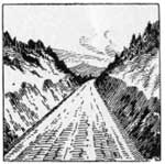
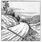
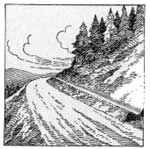
SURFACING Although perfect smoothness of trail surface is desirable, it cannot always be obtained. Surface conditions greatly affect travel speed and utility. Ruts, stones, bumps, and loose surface slow up traffic and cause rapid wear. The best forest truck trails have settled, compact, hard surfaces which are reasonably smooth. Holes are filled in, protruding rocks are removed, and the surface is kept in uniform shape. Surfaced sections, when completed, are level with the unsurfaced shoulders. To obtain this finished level, the subgrade must be trenched out to receive surfacing material. The depth of the trench depends upon the thickness of surfacing material to be applied. Hard rocks, such as trap rocks, limestone, and granite, are better for surfacing than such soft material as schist, sandstone, and slate. Roads which are too sandy may be improved by adding clay. Soils with too much clay may be thinned with sand. Clay or sand, whichever is needed, may be spread over the surface, worked to proper depth with harrow or scarifier, and then compacted by traffic. Gravel or stone may be taken from the pit or bank and applied directly to the truck trail. When this plan is followed the only selective process involved is in choosing a good source and raking away lumps and stones more than 3 inches in diameter. Finer gravel may be obtained by screening or crushing. A good surface may be spoiled by adding too much gravel, especially if no binding material such as clay is used. The United States Forest Service has adopted three standard classes of surfacing: CLASS A (1) For double-track truck trails (20 to 22 feet wide) surfacing is placed in trench 16 feet wide—3 inches of 1-1/2 to 3-inch stone, overlaid with 3 inches of 3/4- to 1-1/2-inch stone, capped with 2 inches of 3/4-inch stone and smaller. (2) For single-track truck trails (13 to 15 feet wide) surfacing is laid in trench 9 feet wide—base of 1-1/2 to 3-inch stone (3 inches deep at outer edges, less in center); next, a layer of 3/4- to 1-1/2-inch stone (2 inches deep at center, 3 at outer edges), capped with uniform layer of 3/4-inch stone and less, 2 inches deep. CLASS B For any truck trail not requiring class A surfacing—one course of 3/4- to 1-1/2-inch stone, 2 or 3 inches deep, topped with 2 inches of 3/4-inch stone or less. CLASS C For any truck trail of low surfacing requirements—2 inches of 3/4-inch stone and finer material, spread evenly in trench 8 feet wide. Shoulders, after they become compacted are treated with 1 inch of fine material, up to 3/4-inch stone, to bring them up to grade. The thicknesses given in the Forest Service classification are those of loose material; the thickness of the finished job will depend upon the amount of compacting done. Stone and gravel are spread with dump trucks and distributed to the required depths with shovels and rakes. Each layer should be compacted before an overtopping layer is added. MAINTENANCE After the truck trail is completed, its life and utility will depend upon efficient maintenance. The frequency of maintenance operations varies with the type and the use of the trail. Intensive going over once in 2 years may be sufficient for low service trails, but high service trails may demand continuous maintenance. In maintaining truck trails, all points of the projects should be inspected and repaired or improved, if necessary. Shovels, scrapers, and graders comprise the equipment generally used. Ditches, culverts, outlets, and inlets are cleaned of all debris and vegetation. Head walls are repaired and erosion is checked on spillways. Culverts that are not working because of improper setting are taken up and reset. Additional culverts or larger ones are placed where drainage has proved inadequate. Ruts and holes are filled and shoulders are built up to grade; the surface is reshaped to conform to standards. Rocks which have been jarred loose by traffic, and those which have descended in slides are removed along with brush or fallen trees that impede travel. Bridges and fill sections are given special care. In short, the work of maintenance is to keep the truck trail "as good as new" or better. |
Surface Must Be Stable.
| |||||
|
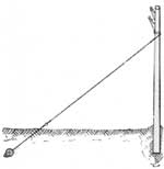
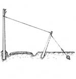
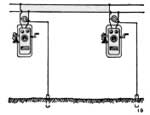
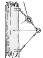
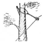
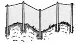
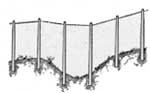
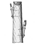
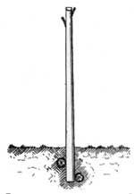
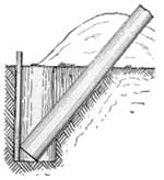
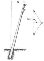
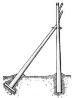
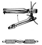
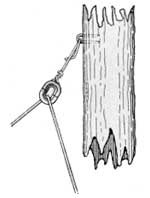
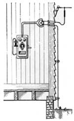
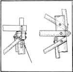
For effective fire control and efficient administration of forest areas of any appreciable size the telephone is an indispensable instrument of communication. Forest areas usually are remote from established telephone systems, or are situated in areas where delays occasioned by "party line" interference decrease their effectiveness. It is necessary, therefore, that forest administrators build their own telephone lines to towers, ranger stations, and guard camps. Two types of telephones are used in the forest—the metallic line and the grounded line. In the metallic line, the current travels outward on one wire and returns on another; but in the grounded line the current travels outward over a single wire and returns through the ground. Construction and maintenance costs of grounded lines are much less than those of metallic lines, and both types of line are equally satisfactory for Forest Service purposes. Grounded lines are used, therefore, wherever practicable in the forest. The simplest grounded line system utilizes trees instead of poles. It consists of a slack wire strung in freely swinging insulators through which the wire may slide in either direction. In the forest where heavy snows, falling branches, or falling trees would break a tightly tied wire, the slack of the tree line permits it to be borne to the ground without breakage, and since communication must be uninterrupted on lines used for reporting fires, it is all-important that the line be nonbreakable. Although the tree line allows sufficient slack to take care of the burden of falling trees and snow, the line should be located, if possible, to avoid such hazards. Exposed sites where high winds are likely to occur, and hillsides subject to landslides or snowslides should also be avoided. For maintenance purposes the line is usually strung along roads or trails so that inspection may be carried out easily. The line should run along the lower sides of roads and railroad tracks to keep broken wire from falling across traffic; and main highways or railroads should not be crossed unless such crossings are unavoidable. Clearing of right-of-way should be at least partially done before the wire is strung. All branches which will come in contact with the line should be removed, including such branches on the tie tree and adjacent trees which may bear on the wire when snow laden. Small trees, beneath the line, which will grow upward to touch the wire are also chopped out. In selecting tie trees (those to which the wire is to be attached) it is important to avoid sharp angles, as these increase the pull on the wire and often cause breakage. To avoid grounding the circuit, the wire should pull away from, rather than toward, the tree. Spans between tie trees vary from 125 to 140 feet, but may be more or less, depending upon the amount of snowfall, kind of topography, and the roads or railways crossed. In any event the span lengths should be equalized as nearly as possible so that the weight of wire in each span will be about the same. Large trees which are difficult to climb are seldom chosen, and species which sprout vigorously are avoided when possible. The wire is strung to a height of about 18 feet at the hanger, but at its lowest point it should not have less than 12-feet ground clearance. The wire should clear the level of the deepest snow, so that it will not be snowed under. Light ladders ordinarily are better than tree climbers, as more uniform and faster work can be done with them. Tree climbers should be included in the field equipment, however, as they are handy for miscellaneous work. Staples, rings, or hooks are used to secure hangers to the trees. Hooks have a special use in keeping the wire from touching the tree when pulling the line toward the tree cannot be avoided. The wire is strung through split insulators with sufficient slack between spans so that the wire may be pulled to the ground with a weight of 75 to 90 pounds. Ties are made strong enough to support the wire under ordinary conditions, but weak enough to break under a 400-pound pull. Thus a falling tree will pull the tie loose and bear the line to the ground rather than break it. On steep slopes the slack is apt to creep down hill if it is not anchored by an occasional solid tie, or "stay tie." In pole lines, 25-foot poles, set about 175 feet apart, are used for straight stretches; but at curves, corners, and other places of unusual strain they may be set as close as conditions warrant. At crossings longer poles may be used to elevate the wire, but such changes of elevation should be gradual. Different length poles should be used to maintain a fairly level line elevation over uneven ground. Poles should be not less than 6 inches in diameter at the top, and of medium taper. The tops are roofed with a half pitch cut to shed water. On poles which bear cross arms the roof ridge is set parallel with the wire line; but on poles which bear brackets, and on which it is not planned to put cross arms later, the roof ridge is placed at right angles to the line. The water shed from the pole roof should not be permitted to soak into the wood near the brackets or cross-arm attachments, as this will hasten decay. In setting out a pole line, the course is staked out so that the line is as straight as possible. Poles are carried out by truck or horse (if good durable poles cannot be found near the proposed site) and are laid near the stakes. Usually the crew is divided into axmen, hole diggers, pole setters, and linemen. The axmen clear a temporary right-of-way which helps mark the line and which facilitates the other operations. With shovels, steel digging bars, or picks, the hole diggers make holes 2-1/2 to 6 feet deep, depending upon the size of the poles and the type of earth. Hole digging and pole setting are made easier if a small trench is dug into the hole, but for small poles this is not necessary. The holes should be large enough, however, to permit tamping the earth around the pole. When the pole is set in the hole, earth is filled in around it and tamped tight. Three tampers, with iron tamping bars, to each shoveller, constitute the usual organization. The earth is tamped until it is solid enough to hold the pole in position. On curves and corners the poles should be given enough "rake" to offset the pull of the line. "Raking" a pole is leaning it away from the line pull. The distance from the top of the pole to a vertical line drawn from its base is the rake. For pulls less than 5 feet (see diagram) the rake should be about 10 inches; 5- to 10-foot pulls require 15-inch rake; and pulls over 10 feet, 25-inch rake. When the pull exceeds 30 feet bracing or guying is necessary. Bracing or guying is also used at road and railroad crossings, on long spans, on steep slopes, in windy sections, on loose or swampy ground, when the line crosses a high tension wire, and on the first and last poles of the line.
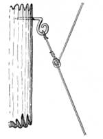
After the poles have been set, the linemen stretch out a half-mile of wire on the ground along the line. They then carry the wire up the poles and place it between the bracket and the pole. Two or three linemen stay on poles along the line while the wire is tightened with a block and special wire grips which do not cut or injure the wire. After the men on the poles signal to the stretcher that the wire is tight enough, they wait a few minutes for the line to adjust itself to an evenly distributed tautness before making a permanent tie. The amount of slack left in the line depends upon the length of the span and the temperature at which the line is strung. Wire expands or contracts with changes of temperature. For instance, if no. 9 galvanized iron wire is strung in a 75-foot span on a hot day (temperature about 100° F.), a sag of about 4-1/2 inches must be left in the span so that the wire will not tighten and break in colder weather. If much slack is left in cold weather the wire will sag too much when the temperature rises. Ties are made of the same size wire as the line wire. (See fig.) |
| |||||
|
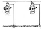
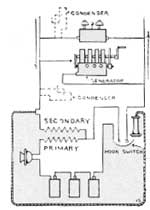
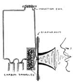
THE TELEPHONE INSTRUMENT To understand why a telephone works, one must have an understanding of the fundamental laws of electricity and magnetism. This discussion is not intended to give the student a complete course in either of those subjects. It is an attempt to explain how, not why, the telephone operates. The best laboratory equipment for studying the telephone is the instrument itself. If possible the student should take a telephone apart to examine: (1) The transmitter, (2) the induction coils, (3) the receiver (4) the generator, and (5) the bell; and to trace the wiring which connects these parts. THE TRANSMITTER When the pressure on two conducting bodies (carbon granules in the transmitter) is increased, more of their surfaces are brought into direct contact, and their combined resistance to current is diminished; and when the pressure is decreased, less of their surfaces are in contact and their combined resistance is increased. The telephone transmitter is based on this principle. The conducting bodies are the carbon granules in the carbon button or capsule behind the diaphragm. Voice tones, when spoken into the transmitter, strike against the diaphragm (a nonmagnetic disk) with sufficient force to apply pressure to the carbon granules and thus increase or decrease their resistance to the electric current flowing from the battery and through the induction coil or "step up" transformer. These changes in resistance regulate the amount of current through the primary of the induction coil and the "induced" current in the secondary that flows from the sending telephone to the receiver at the other end of the line. It is these changing currents that cause a corresponding movement of the receiver diaphragm at the other end, reproducing the voice tones of the sender. THE INDUCTION COIL From the transmitter the current flows to the induction coil, which acts in a manner similar to that of the transformers on the poles of commercial electrical lines. It "steps up" the current through the magnetic action of the primary on the secondary of the induction coil. It is this induced current of higher voltage which flows to the receiver on the other end of the line.
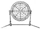
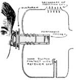
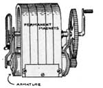
The induced current, arriving at the receiver passes through the coils around its horseshoe magnet and causes a change in the magnetic field. This change, which might be likened to raising and lowering its magnetic properties, causes the magnet to draw the receiver diaphragm closer to it or to drive it away. The movements of the receiver diaphragm correspond to those of the transmitter diaphragm, and since the air in contact with the receiver diaphragm is moved, sound is produced, and the words spoken into the transmitter again become audible in the receiver. The receiver diaphragm is made of soft iron, which responds to magnetic lines of force from the receiver magnets. THE GENERATOR Most rural telephones and those used in the forest are remote from electrically operated lines, and the current for ringing the bell must be generated by a hand crank. The crank turns an armature (a soft-iron core, wound with many turns of fine copper wire) between the poles of a series of three to five horseshoe permanent magnets. The magnets are arranged so that all north poles are on one side, and all south poles are on the other. When the armature is turned the wires cut across the magnetic field between the north and south poles, and an alternating current is set up in the armature wires of sufficient voltage or pressure to ring the bell at the other end of the line.
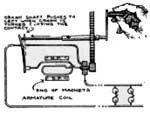
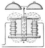
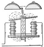
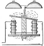
The mechanism that causes the bell to ring consists of a permanent magnet, and an electric magnet. The clapper is rigidly attached to the center of an armature, pivoted on the north end of a permanent magnet. Thus the lines of force from the magnet enter the armature at its center and travel to each end of the armature. Each end of the armature has the properties of a north pole. Beneath the north poles of the armature is a soft iron core, wound with wire. The north poles set up by the armature ends are attracted to these iron cores. If one end of the armature is pressed against one pole of the cores, the armature will stay in that position, since the magnetic field at the other pole has been widened and the attraction thus decreased. When the armature is in this position the clapper rests against one of the bells. The soft iron cores are connected to the generator wires. When the generator is turned, an alternating current is set up which produces a magnet in the coils surrounding the cores, making first a north pole at the right-hand coil and a south pole at the left-hand coil, and then reversing to make a south pole at the right-hand coil and a north pole at the left-hand coil. Changing the polar designation alternately, about 25 times per second, causes the armature to be pulled down first at one end and then at the other, as the south pole on first one coil and then on the other, is alternately strengthened and weakened. This movement of the armature moves the clapper back and forth from one bell to the other.
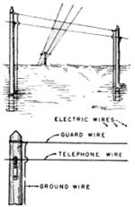
The voice current flowing over the line is so slight that it cannot be felt; and there is no danger of shock from that source. The bell, or ringing, current can be felt, but it, too, does not reach dangerous strength. There are two charges, however, which can reach dangerous proportions and which should be eliminated. One is the electricity which flows along the line when the wire contacts a high tension line. Avoidance of high-tension lines when the telephone line is constructed will eliminate this trouble. Where they cannot be avoided, the proper placing of guard wires will minimize the danger. The other cause of damage to telephone systems is lightning. In regions where lightning storms are prevalent, the line should be protected with a lightning rod and a ground wire on every tenth pole. Arresters of sufficient capacity should be installed at each instrument to prevent lightning from damaging the telephone. |
| |||||
|
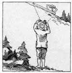
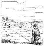
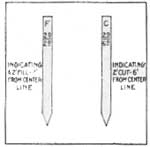
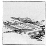
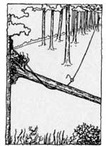
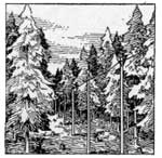
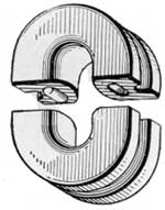
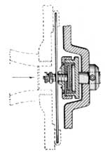
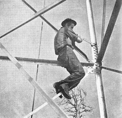
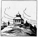
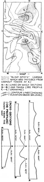
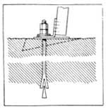
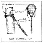
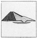
LOOKOUT TOWERS In selecting tower sites, the object is to attain the greatest visibility of the land to be protected. Usually the greatest visibility is attained from the highest peak or ridge. Often, however, the position of the tower on the ridge or peak will determine the view. One end of a long flat ridge may overlook a wider area than does the other end; or the middle of the ridge may combine the advantages of both ends. Topographic maps may be used to determine the relative advantages of various proposed sites. Elevation profiles may be drawn, radiating from the site, as shown in the accompanying sketch. Blind spots (areas not visible from the tower) may be found by drawing a line of sight from the tower's height, over the ridge tops of the profile. Towers are not necessary when the desired visibility can be attained without them. High peaks, or ridges, where the view is not obstructed by trees, may serve as lookout stations, in which case a cabin or other suitable shelter can be erected much more cheaply than a fire tower. STEEL TOWERS For any tower, the placing of anchors or bases is of prime importance. These are the foundations upon which the stability of the tower depends. The piers in which anchor posts are set should be of masonry, concrete, or brick, and should rest firmly upon rock or solid ground. They should be heavy enough to prevent overturning of the tower, and should be at or slightly above the ground level. (See diagram.) The tops of the piers and the anchor rods must be level to prevent a twist in the tower. Perfectly adjusted instruments (levels and transit) and a competent engineer are necessary if a perfect job is expected. Steel towers are manufactured to fit specifications, and bolt holes are drilled so that connecting members fit perfectly without forcing or reaming. Directions for erecting steel towers, and specifications for foundations and guying usually are supplied by the manufacturer. The tower is built up from the foundation, one piece at a time, each horizontal section being completed before the next one is started. After the tower has been completed, it is checked over within a week or two, and all bolts and connections are made tight. Towers over 30 feet in height are sometimes guyed to add greater stability and to prevent toppling. When guy wires are used, they are fastened to each corner at the topmost horizontal member of the tower frame. They are then run through turnbuckles and anchored solidly at least one-half the tower's height away from the tower base.
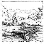
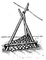
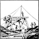
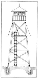
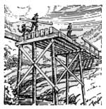
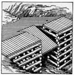
When durable native material can be found, towers may be built of wood. Designs for wooden and steel towers do not differ essentially; and the development of modern connectors for wooden members has increased the safe height to which wood towers may be erected. Radio Station WEBC (Superior, Wis.) has constructed a 350-foot broadcasting tower of which 120 feet is wood. In Meuhlacker, Germany, a wooden tower 625 feet high supports 1,320 pounds of radio antenna. The accompanying illustrations show the construction of log fire towers.
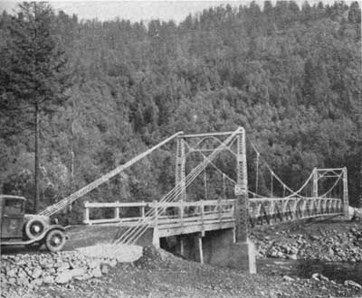
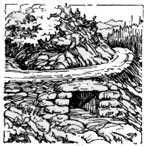
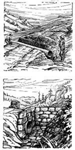
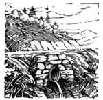
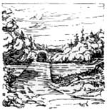
Short-span bridges often may be avoided by the installation of adequate culverts, and culverts provide a smooth, continuous surface, greatly reducing costs. The use to which the truck trail will be put will determine whether fords or bridges will be installed. Future use, when it can be predicted, should be considered in planning bridge construction. Except in cases of unusually large and expensive bridges or very unimportant roads, the bridge should be wherever the road location line crosses the stream, and the bridge should be located to conform with the alinement and grade of the road.
On high-service truck trails, however, bridges should be located on straight stretches, but if these are not obtainable a long radius curve is permissible. Abrupt changes of grade are to be avoided, and the bridge floor should be level. Changes of grade, if unavoidable, should be made far enough away from the bridge to allow an even approach surface. Ordinarily, bridges are constructed with at least 5 feet of clearance above high-water level. This allows logs and uprooted trees to pass under the bridge. Where shallow, sluggish streams are likely to flood, low-water bridges may be built over which the stream may flow in flood seasons. If the downstream side of such bridges is higher than the upstream side the weight of water passing over the bridge tends to hold it to the bottom and reduce the danger of its being washed out. Piers and abutments for bridges may be built of stone, concrete, timber, or a combination of stone and timber known as the stone crib. Often when natural rocky ledges border both sides of the stream, much of the work and cost of building abutments is avoided. Ledges should be inspected thoroughly, however, to see that they have not been undermined or cut away by the water at their bases.
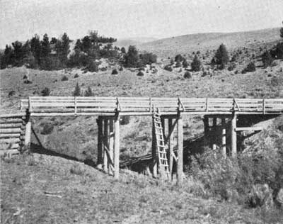
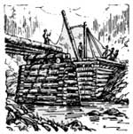
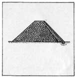
ABUTMENTS STONE ABUTMENTS Dry-stone abutments are not stable enough to bear heavy, rapidly moving traffic, but they may be used for short low little-used spans. Sometimes what may appear to be dry-stone abutments are, in effect, protective walls to reduce scouring of natural banks. In building stone abutments the bank should be cut away to allow a wall to be erected at least one half as thick at the base as it is high. Stones must be selected carefully and projecting points must be removed from the tops and bottoms. To prevent the wall washing out from below, the pier must be based well below the stream bed and preferably on natural bedrock. Wet masonry (that bound together with mortar), is more stable than unbound stone, and piers and abutments of this type may be built up to any necessary height. It is important in laying masonry to establish bond (overlapping of the stones). A series of consecutive vertical joints causes a weak spot in the wall. Square-cut stone, known to engineers as ashlar, is used in fine construction work. Ordinarily however, such expensive construction is not justified in building forest bridges. Unsquared stones, or rubble, is commonly used. Rubble falls into two classes—coursed rubble or that laid in definite layers, and uncoursed rubble or that laid with no attempt to maintain regular courses. In either method the stones are at least rough cut, that is the projecting points and unevennesses are smoothed off to allow as great a bearing surface as possible. In laying stone: 1. Use the largest stones in the foundation and reduce the size gradually toward the top. 2. Place the broad faces down. 3. Overlap all joints. 4. Moisten porous stones before imbedding them in mortar (to keep them from absorbing moisture from the mortar). 5. Fill all spaces between stones with mortar. CRIBBING A combination of wood and stone, known as stone crib, is often used for piers and abutments. It consists of a log frame filled with rocks to give it added weight and stability. Bridges supported in this manner are common in eastern logging sections where low streams must be crossed by logging roads. Such bridges can be constructed cheaply and quickly. When built of strong, durable logs, wooden logging bridges may be serviceable for many years. TRESTLES The supporting members of a trestle are known as bents. When properly constructed, a bent will support a load of 600 pounds for each square inch of average cross-sectional area of the piling. For instance, if the average diameter of the piling is 10 inches, the cross-sectional area is 78.5 inches, and the allowable load is 47,000 pounds (600 by 78.5). WOOD FOR BRIDGES The life of wooden bridges depends largely upon the kind of wood of which they are constructed. In all common native trees, the heartwood is more decay resistant than the sapwood. For stringers, floor beams, and flooring, untreated timber should be at least 80 percent heartwood on any girth; but for caps, sills and posts the timber should contain at least 75 percent heartwood on each of the four sides. (For more detailed descriptions of forest bridges, see The Forest Truck Trail Handbook, structures section.)1 The Forest Service has classified woods for bridge construction in the following groups:
|
See next page.
Nuts and bolts should be checked and tightened as part of tower maintenance. A Firm Foundation Is Necessary.
Bridges Must Clear High Water.
| |||||
|
In forestry work dams are constructed to fulfill one or more of the following purposes: A. Recreation. For large dams, or those which in case of failure would cause loss of life or property, the services of a competent geologist, as well as those of engineers, are necessary to make certain that the ground formations and soil conditions are stable and sufficiently sound to answer the purpose of the proposed dam. The selection of site and the construction of even small dams, except those for erosion prevention, usually require engineering knowledge. There are certain fundamental principles, however, that apply to all forest dams, and with which the forester should be acquainted. The purpose for which the dam is being constructed will be a determining factor in its location and specifications. Recreational dams, for instance, should provide swimming, boating, and fishing in accessible areas where adequate space is available for camping or picnicking. Possible sources of pollution must be obviated or avoided if the water is to be used for swimming or domestic purposes. Dams to provide breeding places and shelter for game and fish must be so situated that they form a part of the game-management plan. Water conserved for irrigation or domestic use should not be too far away from its final point of consumption. Surveys are necessary to coordinate topography with use and construction. Often a good site will not provide an adequate basin, or an adequate basin will not have a good location for the dam. This may be discovered by field inspection, but the surest method is to couple field inspection with a topographic survey of the area. The handbook, Design and Construction of Forest Service Dams, prepared by the United States Forest Service contains detailed information on specifications and construction of spillways and outlets, earth dams, rock-fill dams, concrete and masonry dams, and timber dams. |
Fundamental Principles.
|


| <<< Previous | <<< Contents>>> | Next >>> |
|
ccc-forestry/chap12.htm Last Updated: 02-Apr-2009 |