|
Forest Trail Handbook
|
|
SECTION X.—BRIDGES
54.—LOCATION
Construct bridges only where to avoid construction is impracticable. Never build bridges—
(a) To span streams where reasonably safe fords are available during the field season or where they can be provided.
(b) To span gullies and arroyos if physically practicable to cross them by constructing a trail. Balance cost of trail against cost of bridge.
(c) To improve the alinement of a trail by a relatively small amount.
The Regional Forester should approve the construction of all truss bridges and all stringer bridges. The design of all bridges should be checked and approved by the Regional Engineer. Officers selecting sites and designing bridges need to feel a keen sense of responsibility for the permanency or failure of their work. Failure due to controllable errors calls for the application of the principle of personal accountability.
The chief points that locators and designers of bridges must keep in mind are:
(a) Minimum length of span providing at the same time for:
(1) Stable footing for abutments.
(2) Ample clearance above the water line to provide for free passage of drift logs and uprooted trees.
(3) Advantage of location where the stream is straight and unobstructed.
(4) Minimum cost of new trail for approaches.
(b) Stringers and other members of no less dimensions and in no less numbers than provided in table 5.
(c) Suitable foundations.
(d) Treatment of joints with heavy asphalt paint or some other kind of preservative.
(e) Careful study of all instructions of this chapter before going ahead with the job.
TABLE 5—Minimum number and dimensions of stringers for spans up to 36 feet
| Span in feet |
3-stringer bridge, 6 feet wide |
4-stringer bridge 6 to 7 feet wide | ||||
| Sawed timber | Round timber, diameter |
Sawed timber | Round timber, diameter | |||
| Width | Depth | Width | Depth | |||
| Inches | Inches | Inches | Inches | Inches | Inches | |
| 8 | 3 | 6 | 6 | 3 | 6 | 6 |
| 10 | 3 | 6 | 6 | 3 | 6 | 6 |
| 12 | 3 | 8 | 7 | 3 | 8 | 7 |
| 14 | 3 | 10 | 8 | 3 | 8 | 7 |
| 16 | 3 | 10 | 8 | 4 | 8 | 8 |
| 18 | 4 | 10 | 9 | 4 | 8 | 8 |
| 20 | 4 | 12 | 10 | 4 | 10 | 9 |
| 22 | -- | -- | -- | 4 | 12 | 9 |
| 24 | -- | -- | -- | 4 | 12 | 10 |
| 26 | -- | -- | -- | 6 | 12 | 10 |
| 28 | -- | -- | -- | 6 | 12 | 10 |
| 30 | -- | -- | -- | 6 | 12 | 12 |
| 32 | -- | -- | -- | 8 | 12 | 12 |
| 34 | -- | -- | -- | 8 | 12 | 12 |
| 36 | -- | -- | -- | 8 | 12 | 12 |
When requesting approval and plans for structures from the Regional Engineer, a topographic survey and vicinity map with profile should be prepared, giving the following data:
Vicinity map: Scale 10 feet equals 1 inch. Indicate for 100 feet on each side of center line and 200 feet at each end of approach for proposed crossing. Contours, 5-foot intervals.
Profile: Scale 10 feet horizontal=1 inch; 10 feet vertical=1 inch.
Depth to bedrock for piers or abutments.
Character of material at approaches.
Location of nearest sand and gravel deposits.
Location of nearest suitable timber.
Estimated cost.
Where special designs are requested and field personnel is not qualified to make the proper surveys, the Regional Engineer should be requested to make the survey and selection of bridge for the crossing proposed.
Construction details as to material used, sizes of members, etc., as outlined on the plans should be followed closely, or where materials for span are not available, and other materials used, approval of the Regional Engineer should be obtained before substitution is made.
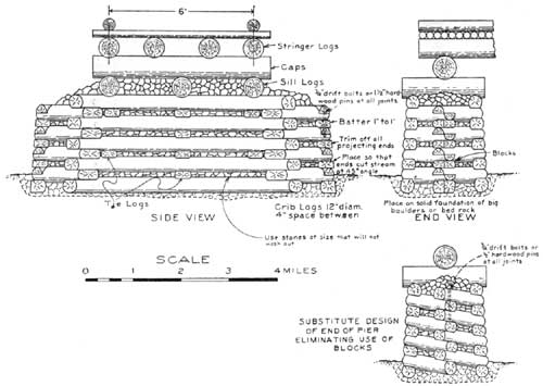
55.—STRINGER BRIDGES
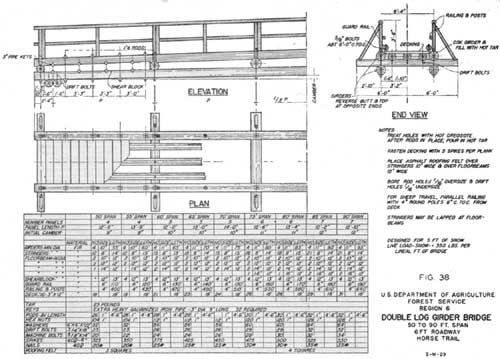
Stringer bridges will be used in the great majority of cases where construction is done by the regular trail crew. Figures show the approved types to serve as a guide. Six feet is standard width for the floor. This will be exceeded only where use of large stringers make it necessary. Observe the following in every case:
(a) Use rock for abutments and foundations in preference to logs, where possible.
(b) Where abutments and sills are of wood, they should be of the most rot-resistant species available.
(c) Fills around logs should be of rock and not earth. This permits drainage and reduces rate of decay.
(d) Always peel the bark off the logs.
(e) Wood pins or tree nails may be used in place of iron driftpins.
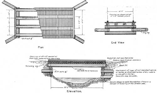
(f) If round material is used for flooring, hew tread along center line. Figure 33 shows a satisfactory floor. Do not put a dirt covering over the floor.
(g) Flooring on three-stringer bridges must be at least equal in strength to that of 2- by 12-inch planks.
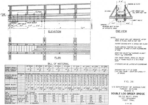
(h) Use four stringers in heavy snow country and where timber is small; also, where span is over 20 feet.
(See figures 33, 35, 36, 37, and 38.)
|
| FIGURE 33. (click on image for a PDF version) |
|
| FIGURE 34. (click on image for a PDF version) |

|
| FIGURE 35. (click on image for a PDF version) |
|
| FIGURE 36. (click on image for a PDF version) |
|
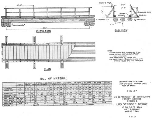
| FIGURE 37. (click on image for a PDF version) |
|
| FIGURE 38. (click on image for a PDF version) |
The calculations in table 5 were based on a uniform load of 400 pounds per linear foot of span. A maximum bending stress of 1,200 pounds per square inch was used.
The round-timber diameters are to be measured at the small end after deducting one-half of the diameter of the sapwood.
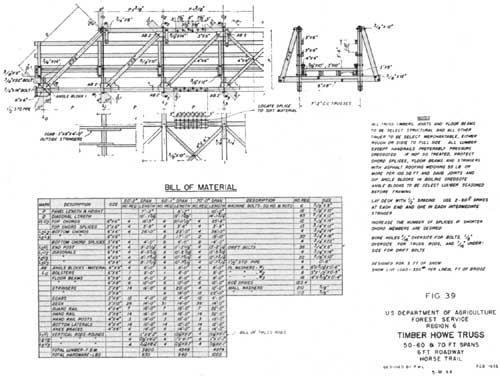
56.—TRUSS BRIDGES
Truss bridges should be used only when stringers of adequate dimensions cannot be obtained. The cost is much higher than for a stringer bridge and, unless accurately framed, only a small portion of the theoretical strength is developed.
Where the snow is exceptionally heavy and portions of the floor cannot be removed conveniently in the fall, a truss bridge may be necessary to avoid permanent sag in a simple stringer type.
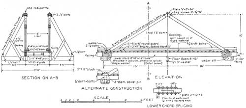
Figures 34, 39, and 40 show approved plans of this kind of bridge. The same general rules are to be observed here as with stringer bridges.
|
| FIGURE 39. (click on image for a PDF version) |

|
| FIGURE 40. (click on image for a PDF version) |
|
| FIGURE 41. (click on image for a PDF version) |
|
| FIGURE 42. (click on image for a PDF version) |
|
| FIGURE 43. (click on image for a PDF version) |
|
| FIGURE 44. (click on image for a PDF version) |
57.— BRIDGE INSPECTION
Inspection of trail bridges should be made each year. This inspection should cover:
(a) Scour or washouts around piers or abutments.
(b) Timber inspection—breaks, splitting, rot, paint.
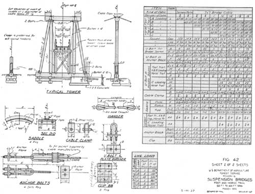
(c) Suspension bridges:
(1) Cable curves uniform.
(2) Evidence of sagging.
(3) Broken wires and surface rust.
(4) Anchorage and towers.
Signs of slipping or failure in masonry or dead man locations.
Rot, breaks, paint.
(5) Bolts tight on all rods and bearings.
Where inspection indicates repair or replacement is necessary, such maintenance and repair should be made as quickly as possible.
| <<< Previous | <<< Contents>>> | Next >>> |
|
forest-trail-handbook/sec10.htm Last Updated: 04-Jan-2010 |