ARLINGTON HOUSE
Historic Structures Report
Phase II
|

|
APPENDIX VI
NORTH WING PHYSICAL INVESTIGATION
NORTH WING PHYSICAL INVESTIGATION
THE ARLINGTON HOUSE
GEORGE WASHINGTON MEMORIAL PARKWAY
by
S. Elizabeth Sasser
Technical Advisor
James S. Askins
Denver Service Center
Williamsport Preservation Training Center
July 1985
I. INTRODUCTION
This report details the findings of a program of
limited destructive investigation in the north wing of the Arlington
House, conducted in May 1985, by the Williamsport Preservation Training
Center. The purpose of the investigation was to attempt to resolve
questions relating to the origins and evolution of the north wing,
raised by architectural features uncovered during structural
stabilization work (1980-1981), and research for the
Historic Structure Report (Architectural Data Section, Phase II, Arnest
and Sligh, 1983). Extensive fabric removal in the course of the
structural and investigative work revealed unanticipated evidence of a
complex and largely undocumented history of construction changes.
It was determined on the basis of this evidence that
the north wing existed in some form as a freestanding structure prior to
completion of the central block and loggia; that the originally
constructed first floor elevation was approximately five feet higher
than the existing; and that there were major changes in openings,
partition arrangement, and fireplace locations. However, integration of
this evidence into an evolutionary sequence and chronology of
construction is complicated by the obliteration of much early fabric in
the implementation of the design program for the mansion as a whole, and
in subsequent phases of alteration, repair and attempted restoration.
Primary architectural evidence usually found at floor and ceiling level
was destroyed during the Department of the Army program of restoration
(c. 1906-1929). Also, the continuity of architectural finishes was
severely disrupted by general repairs and the introduction of plaster
patches over expanded metal lath at all partition/wall intersections.
Therefore, the extant evidence relating to early periods of construction
is fragmentary and isolated in context. The current lack of sufficient
historical documentation to support positive identification of period
features, particularly those relating to the interpretive period (c.
1861), further complicates the interpretation of physical evidence.
In December 1984, at the request of the Park, the
Williamsport Preservation Training Center conducted an evaluation of the
physical evidence uncovered in the previous phase of work. After four
weeks of onsite investigation by Jim Askins, Chief, WPTC, assisted by
Historical Architect, Elizabeth Sasser and Preservation Trainee, Barry
Caldwell, it was concluded that the evidence as it was then understood
was insufficient to determine the original extent and form of the
structure, or the evolution and dating of interior partition
arrangements. There fore it was recommended that additional, limited
destructive investigation be completed, with the following
objectives:
— To establish the original building
limits and siting of the north wing in its earliest configuration as a
freestanding structure. This was felt to be a critical indicator of
whether the building was a pre-existing structure of unknown
function and appearance, adapted for use, or was constructed by GWP
Custis as an element of the design concept for the mansion as a whole,
as attributed to architect George Hadfield.
— To determine the nature and location of
any fenestration predating the existing, and to establish whether
existing fenestration represents original construction.
— To further establish the location and
sequence of partitions predating the existing, and aid in developing
other sequences in finish construction.
This proposal forms the basis for the architectural
investigation detailed in this report. It should be noted that this is
not a comprehensive treatment of conditions in the north wing. The
present work was completed in conjunction with the revision of the
Historic Structure Report, Architectural Data Section, for which it is
to serve as an addendum, dealing only with the issues outlined above. A
number of questions relating to the dating of the loggia, bathroom, and
the nature of interpretive period cooking arrangements were beyond the
scope of the present investigation. Finally, the author gratefully
acknowledges the assistance and many kindnesses shown by the entire
staff of the Arlington House, particularly Staff Curator, Agnes
Mulliins, during the course of the investigation.
METHODOLOGY
The investigation procedure consisted of removal of
an 8 inch wide band of plaster down to brick, extending completely
around the interior of the perimeter wall of the north wing. The 8 inch
width of the plaster band represents 3 courses of brick, which was felt
to be the minimum necessary to identify construction joints or major
changes in masonry rhythm. The height of the plaster band was set at
approximately 90 inches above the existing floor, or 30 inches above the
previous, higher floor level. This was done to intersect potential
infilled opening relating to the earlier floor elevation. As the
investigation proceeded, the height of the plaster band was adjusted
upward slightly in several locations to avoid disturbing significant
concentrations of extant wallpaper, and to maximize the potential
for encountering infilled openings.
Plaster removal was completed one coat at a time on
each wall. Representative samples of each plaster type were labeled with
the area from which they were taken and accessioned by the Park into
their permanent artifact collection. Several areas of plaster showing
significant concentrations of wallpaper fragments were left in
situ. Where incident wallpaper fragments were encountered within the
confines of the plaster band, they were photographically recorded before
removal. Every attempt was made to remove them with the entire thickness
of plaster backing intact. These also were labeled and given to the Park
to be accessioned.
PRESENTATION OF PHYSICAL EVIDENCE
The format chosen for the presentation of physical
evidence was adopted for two reasons. First, to simplify discussion of
the features by placing them in a visual context. The drawings were
intended to highlight key features by reducing the mass of superfluous
detail. Despite the limitations of recording a three dimensional space
in two dimensions, it is hoped that the photographs will assist the
reader in making an independent evaluation of the narrative analysis
accompanying the drawings. Also, in the event that future treatment of
the structure renders the physical evidence inaccessible, this approach
provides at least a partial graphic record of existing conditions.
GLOSSARY OF PLASTER TERMS
series—an application of plaster in one or more
coats, of which the outermost is intended as a finish coat in a specific
period.
coat—a single layer application of plaster over
a surface.
rough coat—the first coat in three coat
plaster work. The term is used here in preference to the contemporary
term "scratch coat" due to the fact that no
raked base coats were found in the north wing.1
brown coat—The second coat in three coat
plaster work. It should be noted that this term is not a reference to
plaster color.
finish coat—The third and final coat in a
three coat plaster series, forming either the final finish condition for
the wall or a substrate for paint or wallpaper.
scored coat—A plaster surface which has
been hacked with a tool such as a plasterer's axe after the plaster has
set, to form a key for adhesion of subsequent layers of plaster.
1. Harley J. McKee. Introduction to Early
American Masonry. (Washington, D.C.: National Trust for Historic
Preservation, 1973), p. 86.
|
|
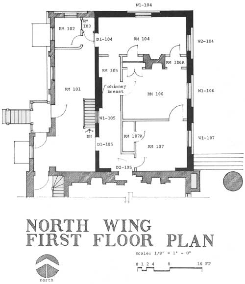
North Wing first Floor Plan (click on
image for a PDF version)
|
II. PHYSICAL EVIDENCE
NOTE: Letter designations indicating a sequence of
plaster series apply only to the page on which they are shown, and do
not represent a general sequence throughout the north wing.
|
|
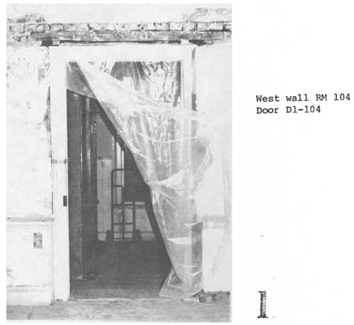
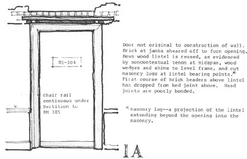
1 West wall RM 104 Door D1-104
|
|
|
1A
|
|
|
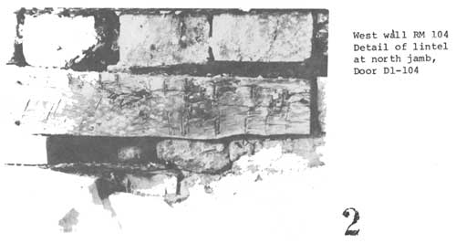
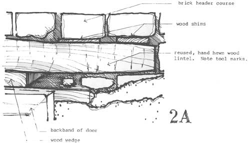
2 West wall RM 104. Detail of lintel at north jamb, Door D1-104
|
|
|
2A
|
|
|
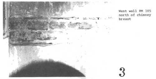
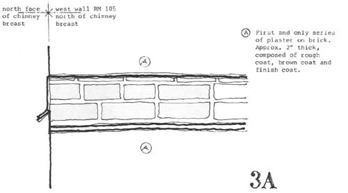
3 West wall RM 105 north of chimney breast.
|
|
|
3A
|
|
|
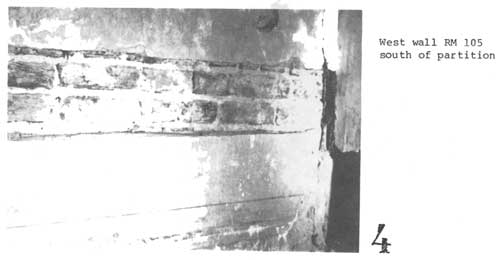
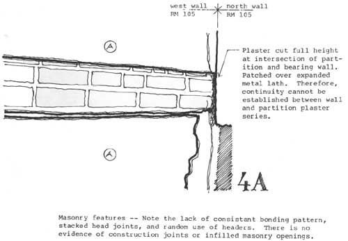
4 West wall RM 105 south of partition.
|
|
|
4A
|
|
|
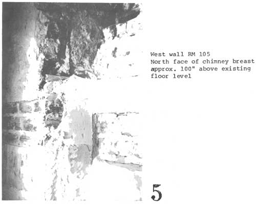
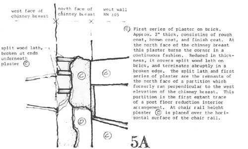
5 West wall RM 105 North face of chimney breast approx.
100" above existing floor level.
|
|
|
5A
|
|
|
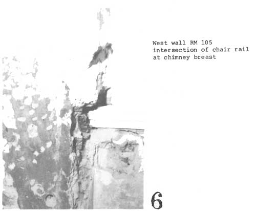
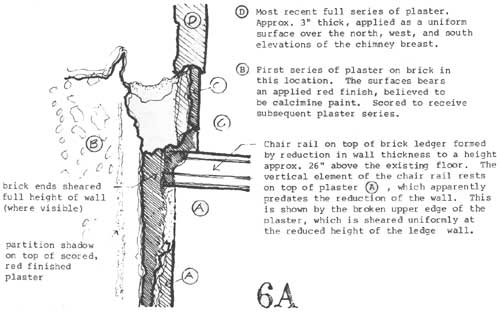
6 West wall RM 105 intersection of chair rail at chimney breast
|
|
|
6A
|
|
|
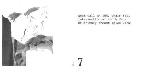
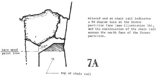
7 West wall RM 105, chair rail intersection at north face of
chimney breast (plan view).
|
|
|
7A
|
|
|
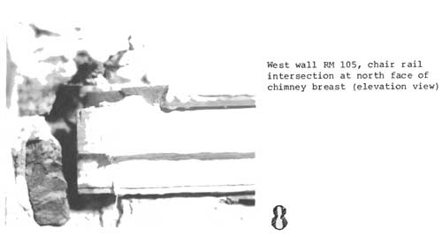
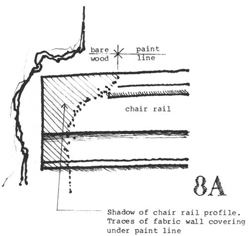
8 West wall RM 105, chair rail intersection at north face of
chimney breast (elevation view).
|
|
|
8A
|
|
|
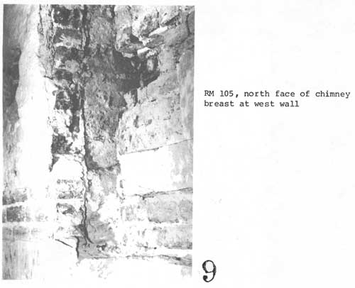
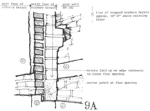
9 RM 105, north face of chimney breast at west wall.
|
|
|
9A
|
|
|
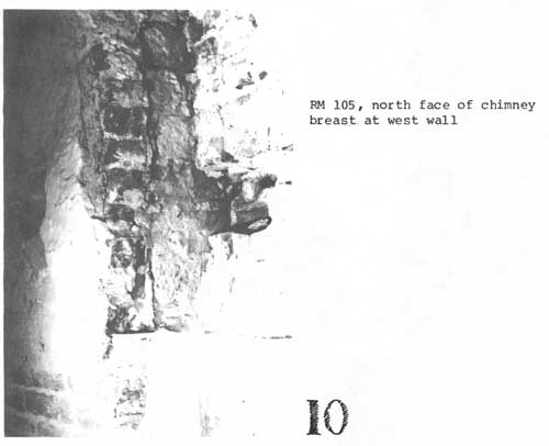
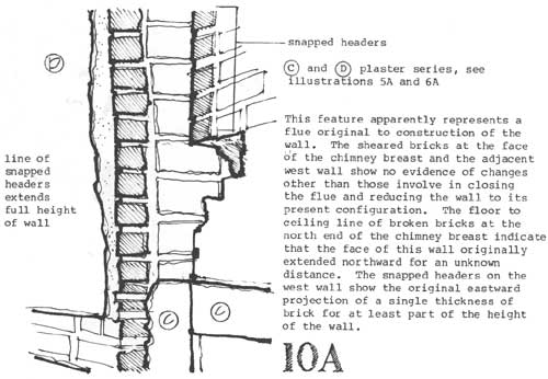
10 RM 105, north face of chimney breast at west wall.
|
|
|
10A
|
|
|
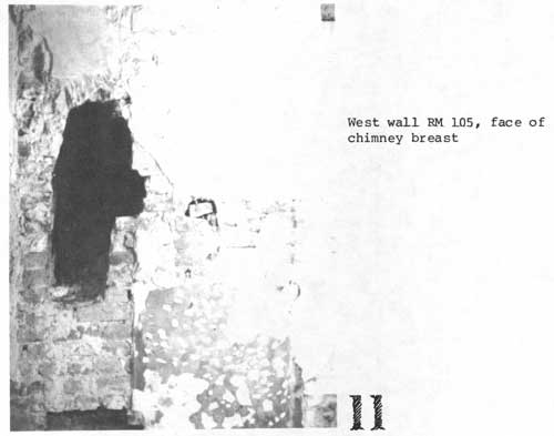
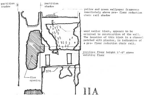
11 West wall RM 105, face of chimney breast.
|
|
|
11A
|
|
|
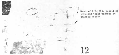
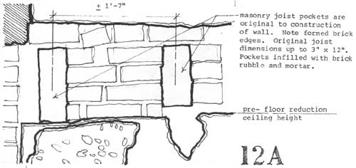
12 West wall RM 105, detail of infilled joist pockets at chimney breast.
|
|
|
12A
|
|
|
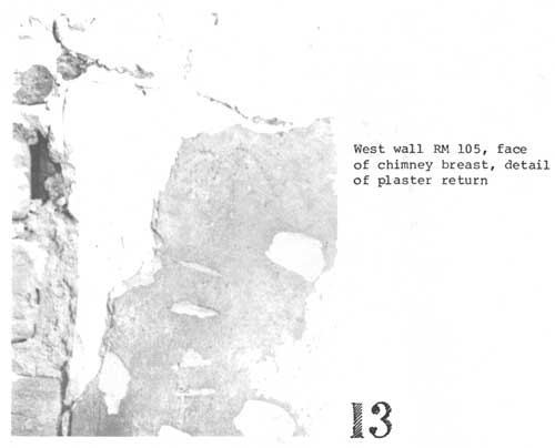
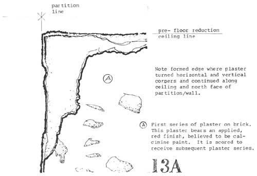
13 West wall RM 105, face of chimney breast, detail of plaster return.
|
|
|
13A
|
|
|
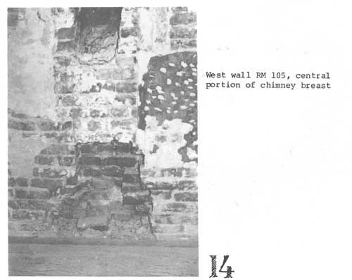
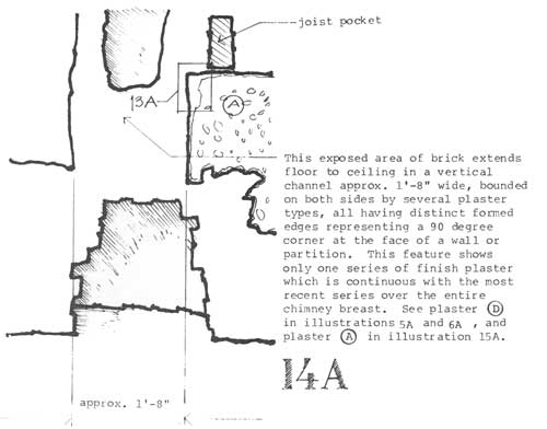
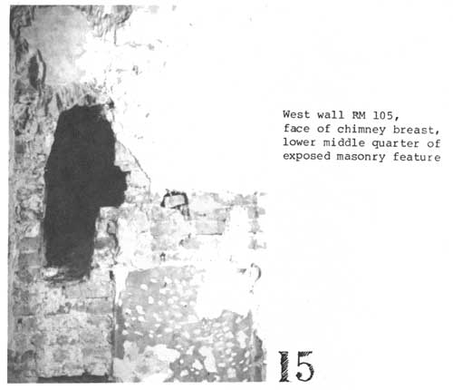
14 West wall RM 105, central portion of chimney breast.
|
|
|
14A
|
|
|
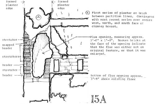
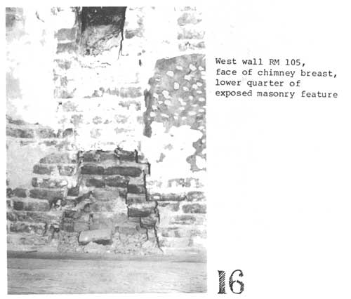
15 West wall RM 105, face of chimney breast, lower middle
quarter of exposed masonry feature.
|
|
|
15A
|
|
|
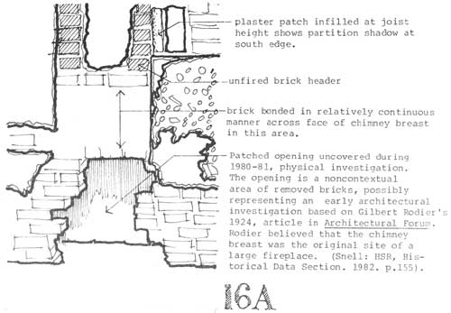
16 West wall RM 105, face of chimney breast, lower quarter
of exposed masonry feature.
|
|
|
16A
|
|
|
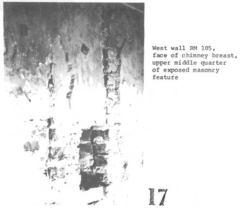
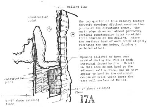
17 West wall RM 105, face of chimney breast, upper middle quarter
of exposed masonry feature.
|
|
|
17A
|
|
|
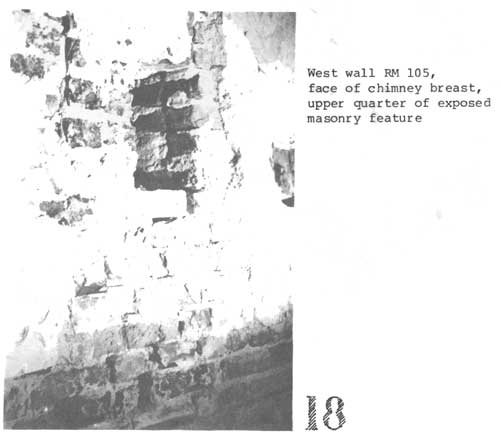
18 West wall RM 105, face of chimney breast, upper quarter of
exposed masonry feature.
|

|
|
18A
|
|
|
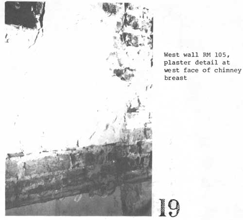
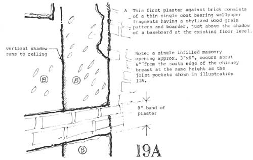
19 West wall RM 105, plaster detail at west face of chimney breast.
|
|
|
19A
|
|
|
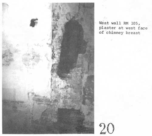
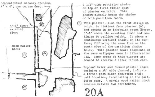
20 West wall RM 105, plaster at west face of chimney breast.
|
|
|
20A
|
|
|
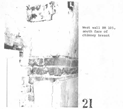
21 West wall RM 105, south face of chimney breast.
|
|
|
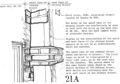
21A
|
|
|
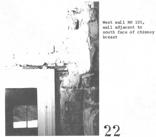
22 West wall RM 105, wall adjacent to south face of chimney
breast.
|
|
|
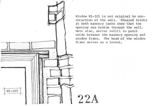
22A
|
|
|
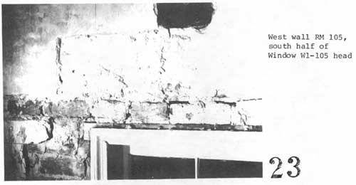
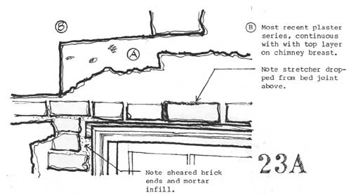
23 West wall RM 105, south half of Window W1-105 head.
|
|
|
23A
|
|
|
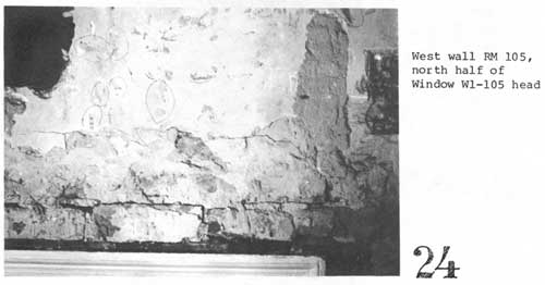
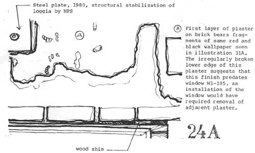
24 West wall RM 105, north half of Window W1-105 head.
|
|
|
24A
|
|
|
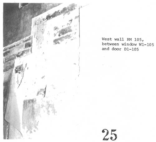
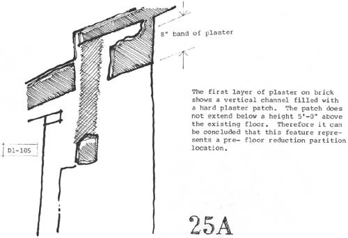
25 West wall RM 105, between window W1-105 and door D1-105.
|
|
|
25A
|
|
|
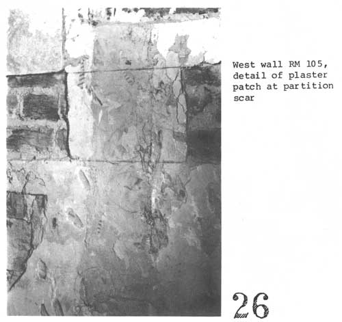
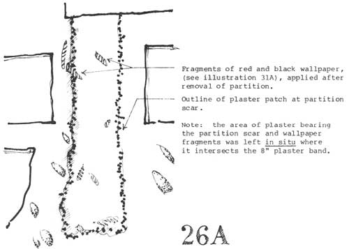
26 West wall RM 105, detail of plaster patch at partition scar.
|
|
|
26A
|
|
|
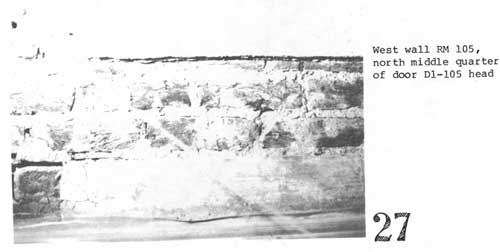
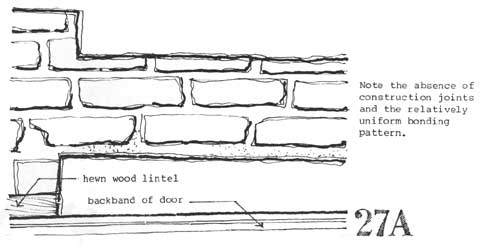
27 West wall RM 105, north middle quarter of door
D1-105 head.
|
|
|
27A
|
|
|
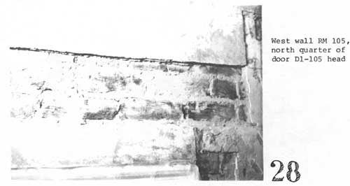
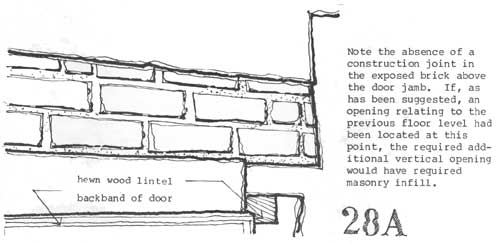
28 West wall RM 105, north quarter of door D1-105 head.
|
|
|
28A
|
|
|
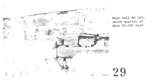
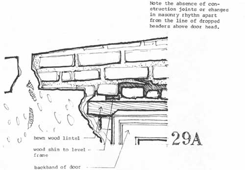
29 West wall RM 105, south quarter of door D1-105 head.
|
|
|
29A
|
|
|
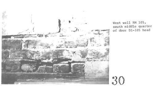
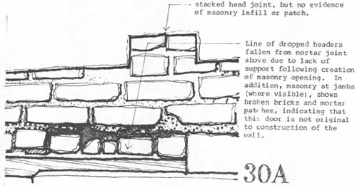
30 West wall RM 105, south middle quarter of door D1-105 head.
|
|
|
30A
|
|
|
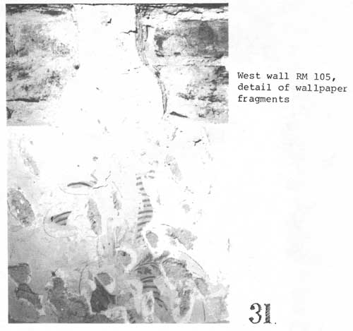
31 West wall RM 105, detail of wallpaper fragments.
|
|
|
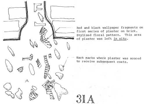
31A
|
|
|
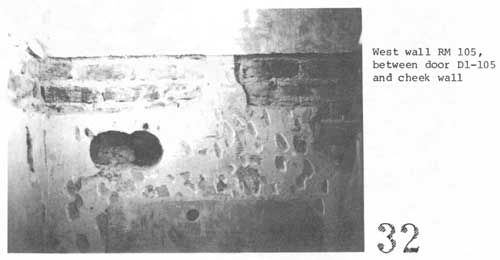
32 West wall RM 105, between door D1-105 and cheek wall.
|
|
|
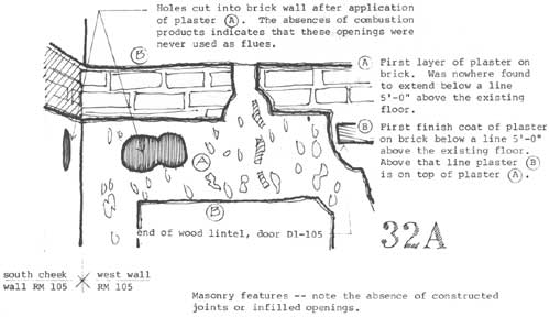
32A
|
|
|
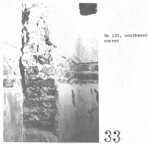
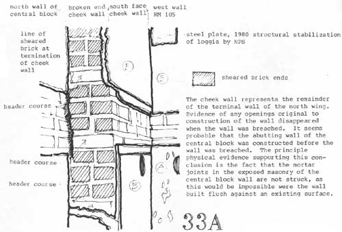
33 RM 105, southwest corner.
|
|
|
33A
|
|
|
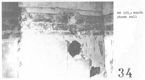
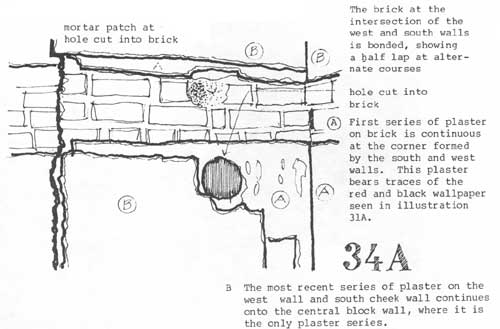
34 RM 105, south cheek wall.
|
|
|
34A
|
|
|
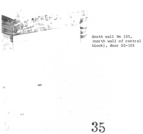
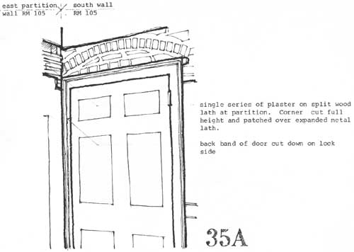
35 South wall RM 105, (north wall of central block), door D2-105.
|
|
|
35A
|
|
|
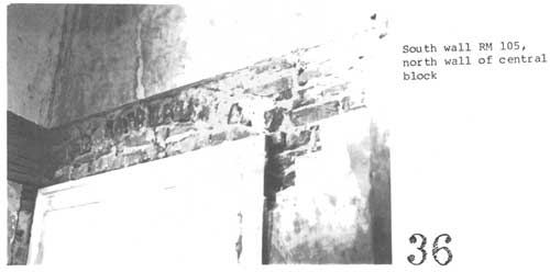
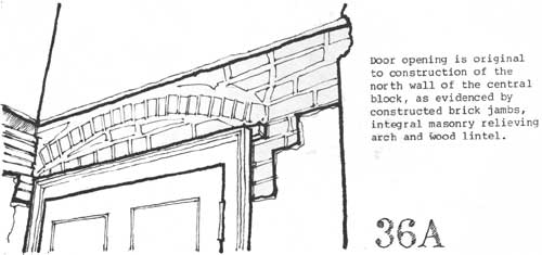
36 South wall RM 105, north wall of central block.
|
|
|
36A
|
|
|
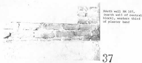
37 South wall RM 107, (north wall of central block), western
third of plaster band.
|
|
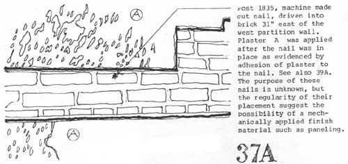
|
37A
|
|
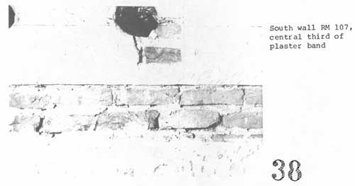
|
38 South wall RM 107, central third of plaster band.
|
|
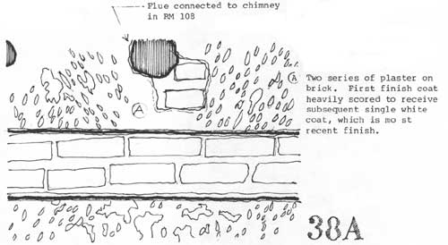
|
38A
|
|
|
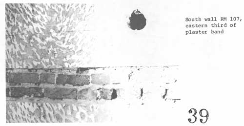
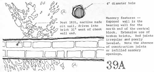
39 South wall RM 107, eastern third of plaster band.
|
|
|
39A
|
|
|
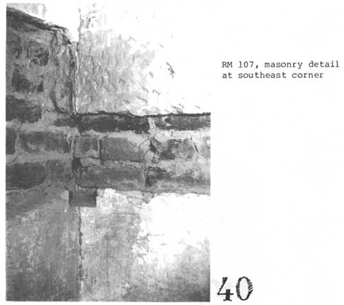
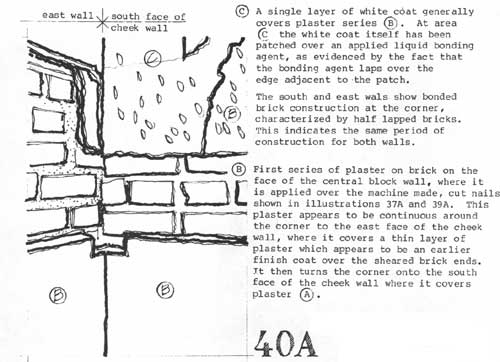
40 RM 107, masonry detail at southeast corner.
|
|
|
40A
|
|
|
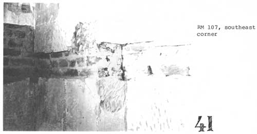
41 RM 107, southeast corner.
|
|
|
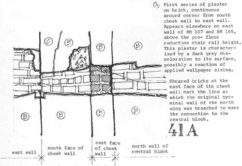
41A
|
|
|
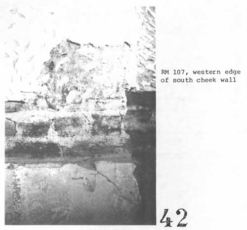
42 RM 107, western edge of south cheek wall.
|
|
|
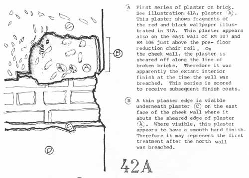
42A
|
|
|
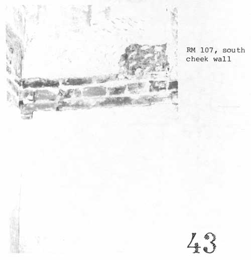
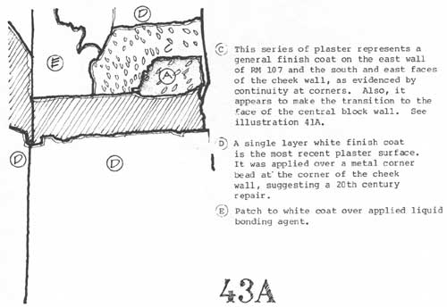
43 RM 107, south cheek wall.
|
|
|
43A
|
|
|
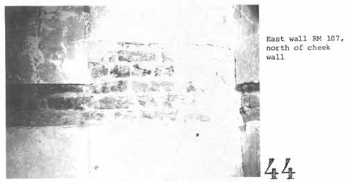
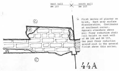
44 East wall Rm 107, north of cheek wall.
|
|
|
44A
|
|
|
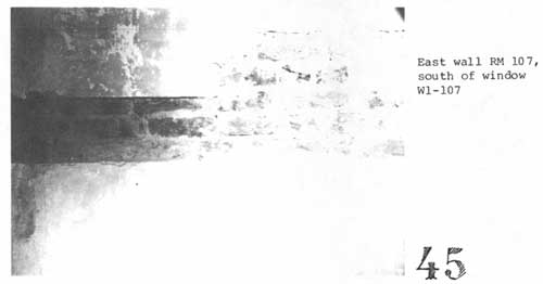
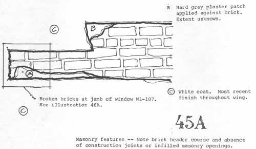
45 East wall RM 107, south of window W1-107.
|
|
|
45A
|
|
|
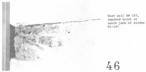
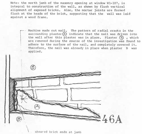
46 East wall RM 107, exposed brick at south jamb of window W1-107.
|
|
|
46A
|
|
|
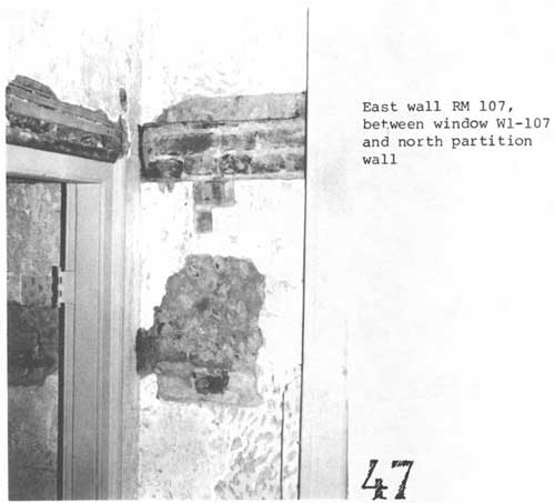
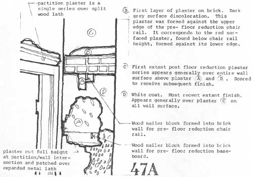
47 East wall RM 107, between window W1-107 and north partition wall.
|
|
|
47A
|
|
|
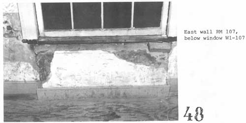
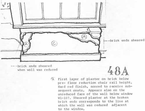
48 East wall RM 107, below window W1-107.
|
|
|
48A
|
|
|
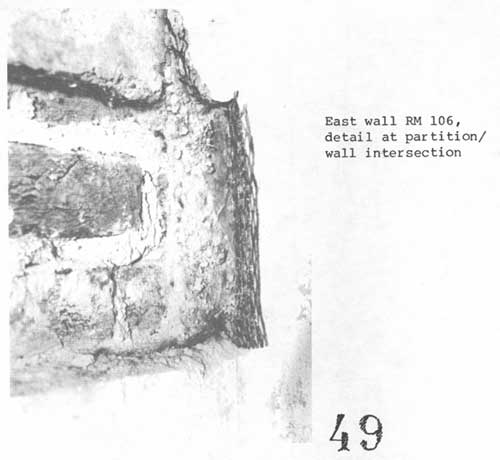
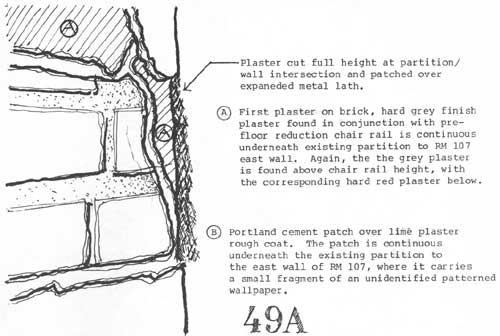
49 East wall RM 106, detail at partition/wall intersection.
|
|
|
49A
|
|
|
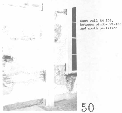
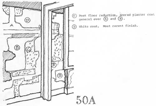
50 East wall RM 106, between window W1-106 and south partition.
|
|
|
50A
|
|
|
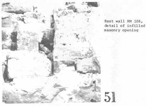
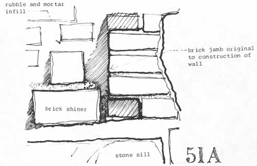
51 East wall RM 106, detail of infilled masonry opening.
|
|
|
51A
|
|
|
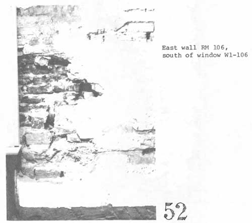
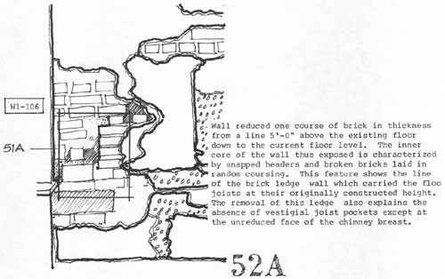
52 East wall RM 106, south of window D1-106.
|
|
|
52A
|
|
|
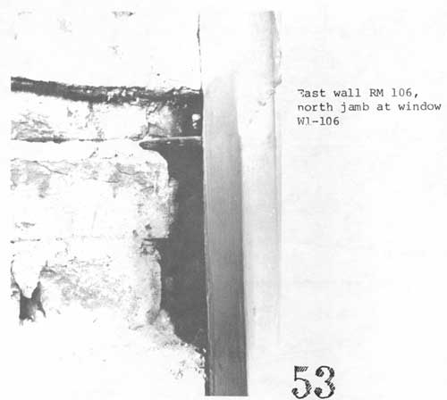
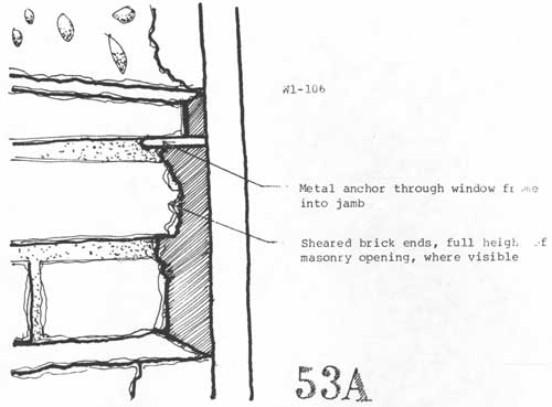
53 East wall RM 106, north jamb at window W1-106.
|
|
|
53A
|
|
|
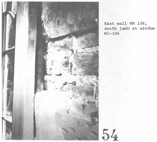
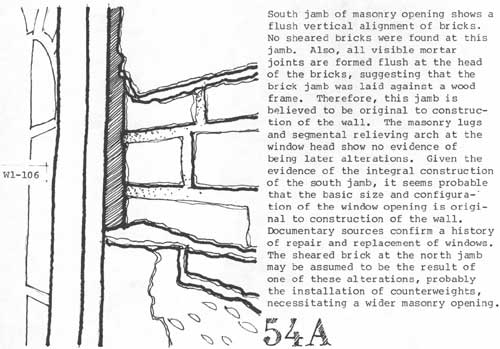
54 East wall RM 106, south jamb at window W1-106.
|
|
|
54A
|
|
|
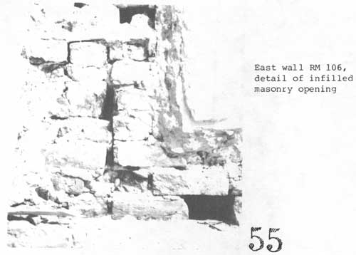
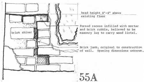
55 East wall RM 106, detail of infilled masonry opening.
|
|
|
55A
|
|
|
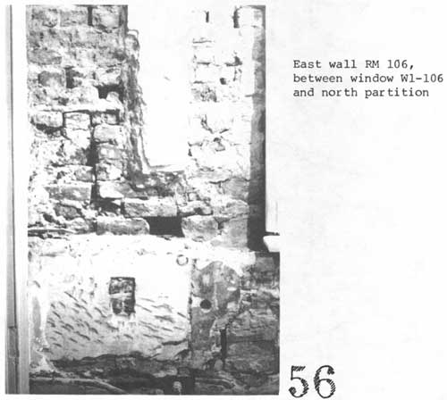
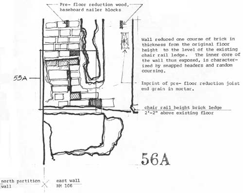
56 East wall RM 06, between window W1-106 and north partition.
|
|
|
56A
|
|
|
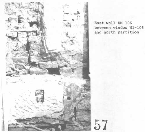
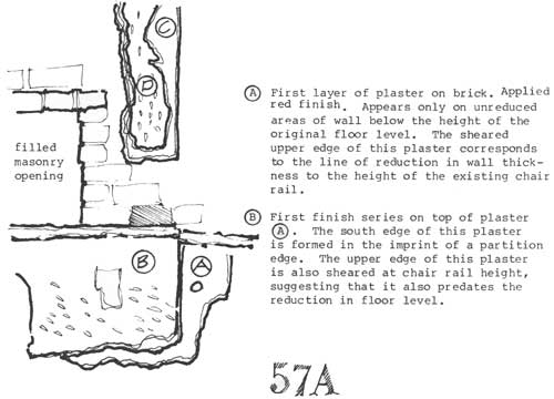
57 East wall RM 106, between window W1-106 and north partition.
|
|
|
57A
|
|
|
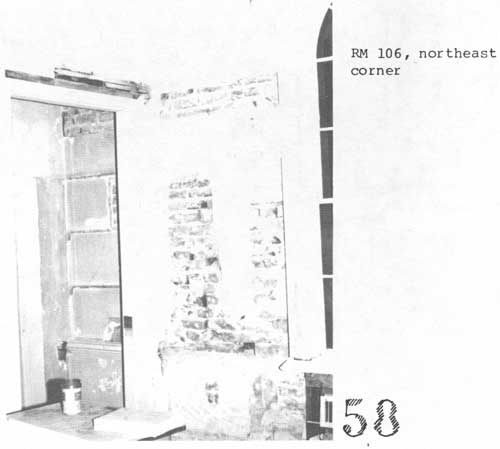
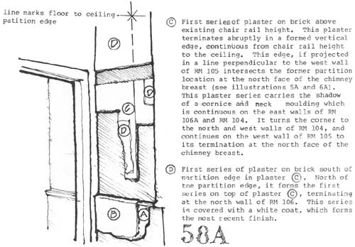
58 RM 106, northeast corner.
|
|
|
58A
|
|
|
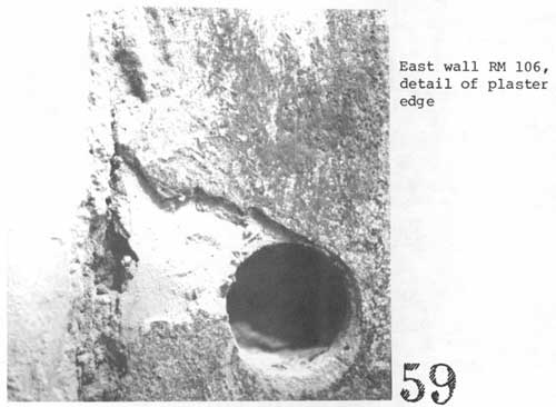
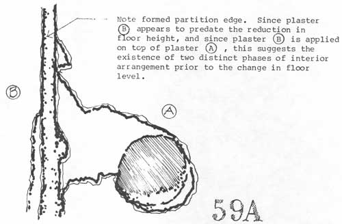
59 East wall RM 106, detail of plaster edge.
|
|
|
59A
|
|
|
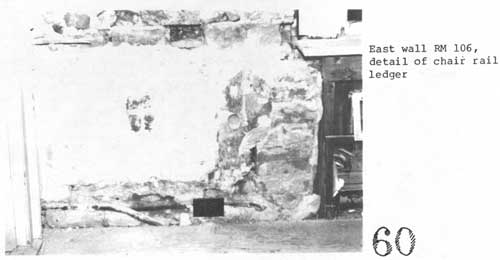
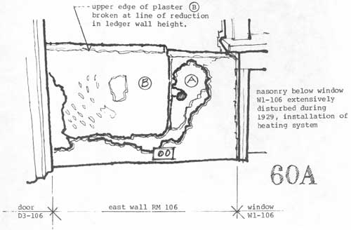
60 East wall RM 106, detail of chair rail ledger.
|
|
|
60A
|
|
|
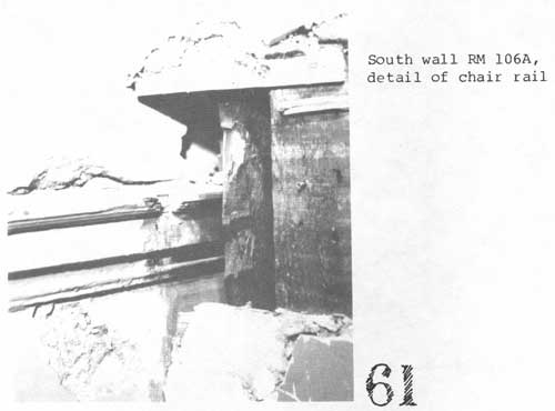
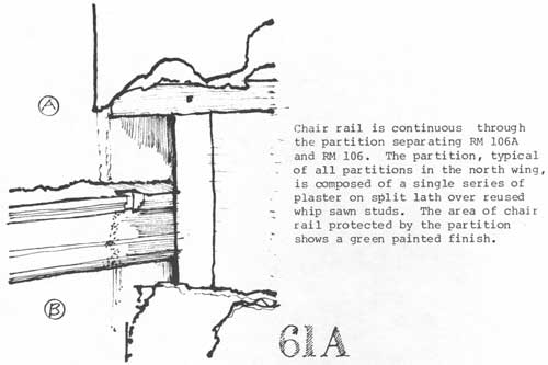
61 South wall RM 106A, detail of chair rail.
|
|
|
61A
|
|
|
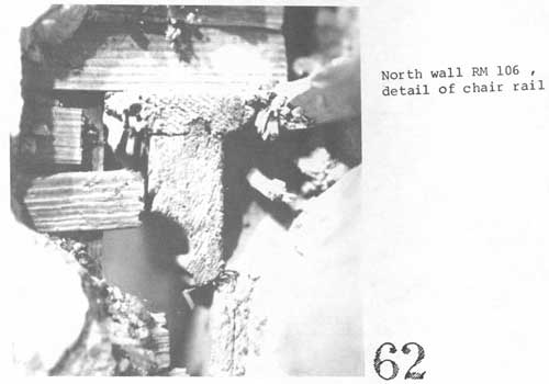
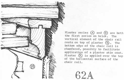
62 North wall RM 106, detail of chair rail.
|
|
|
62A
|
|
|
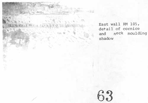
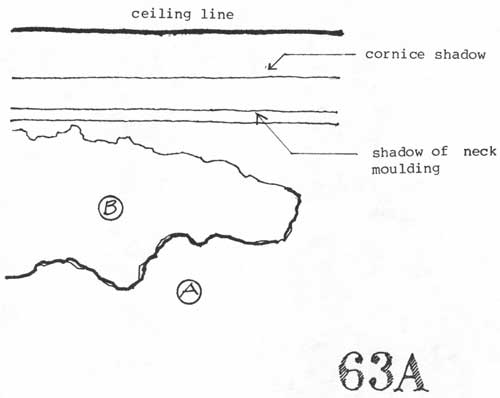
63 East wall RM 105, detail of cornice and neck moulding shadow.
|
|
|
63A
|
|
|
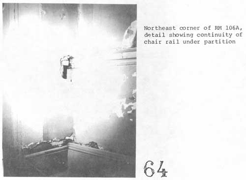
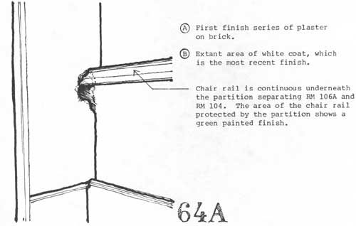
64 Northeast corner of RM 106A, detail showing continuity of chair
rail under partition.
|
|
|
64A
|
|
|
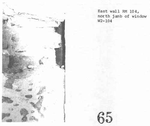
65 East wall RM 104, north jamb of window W2-104.
|
|
|
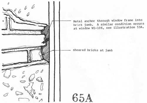
65A
|
|
|
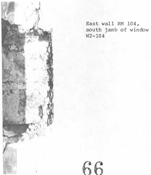
66 East wall RM 104, south jamb of window W2-104.
|
|
|
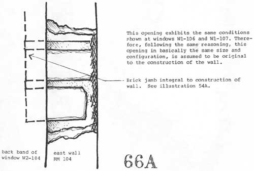
66A
|
|
|
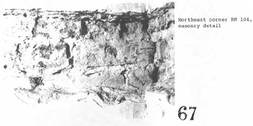
67 Northeast corner RM 104, masonry detail.
|
|
|
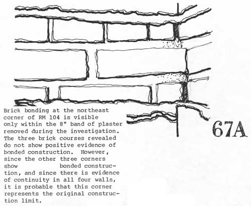
67A
|
|
|
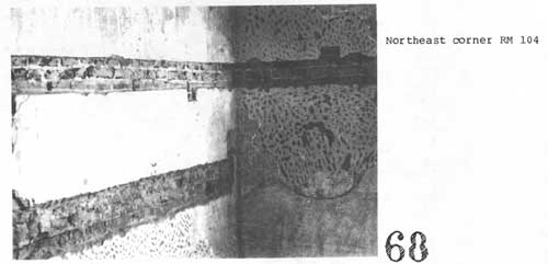
68 Northeast corner RM 104.
|
|
|
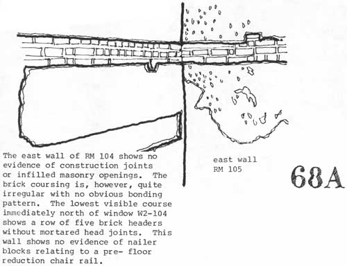
68A
|
|
|
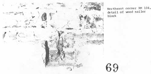
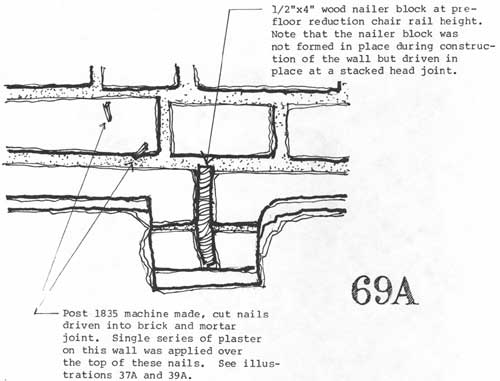
69 Northeast corner RM 104, detail of wood nailer block.
|
|
|
69A
|
|
|
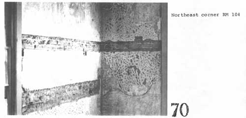
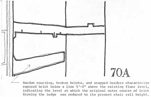
70 Northeast corner RM 104.
|
|
|
70A
|
|
|
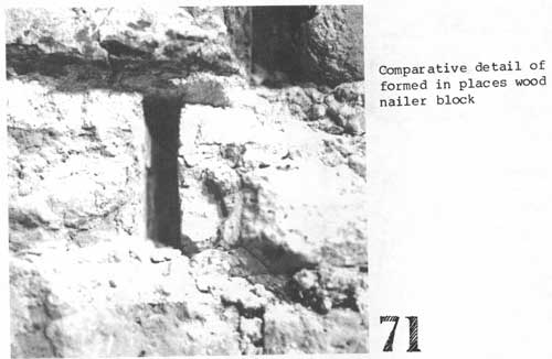
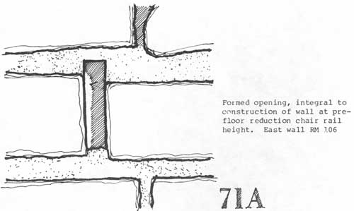
71 Comparative detail of formed in places wood nailer block.
|
|
|
71A
|
|
|
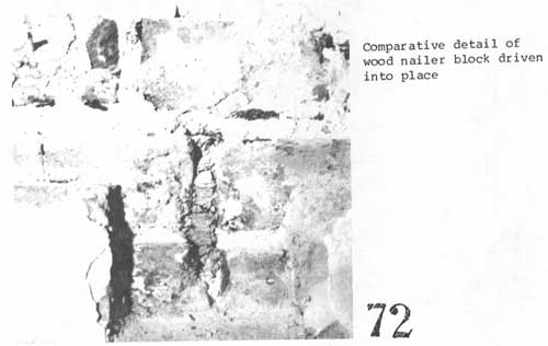
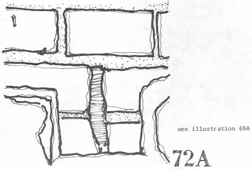
72 Comparative detail of wood nailer block driven into place.
|
|
|
72A
|
|
|
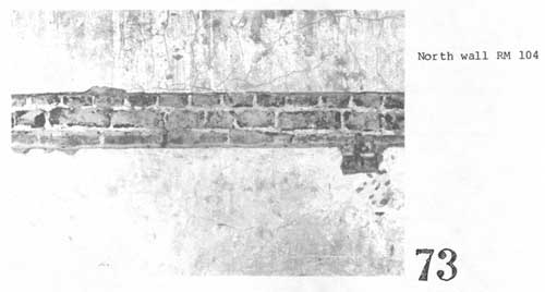
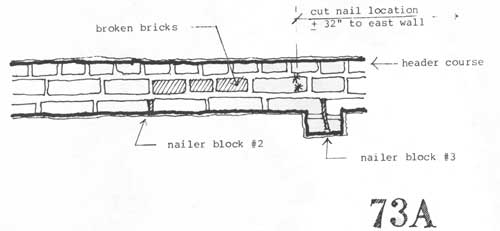
73 North wall RM 104.
|
|
|
73A
|
|
|
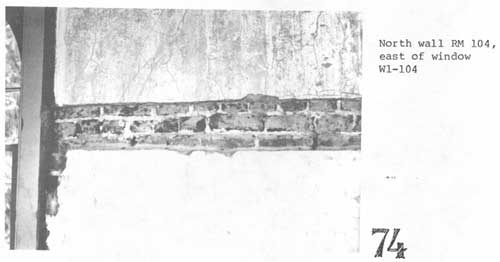
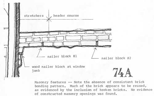
74 North wall RM 104, east of window W1-104.
|
|
|
74A
|
|
|
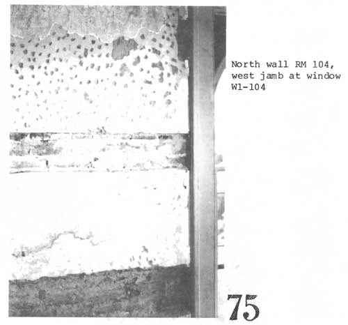
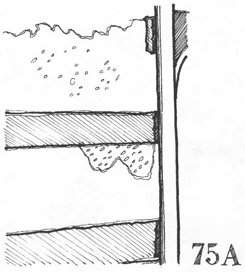
75 North wall RM 104, west jamb at window W1-104.
|
|
|
75A
|
|
|
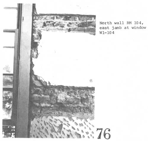
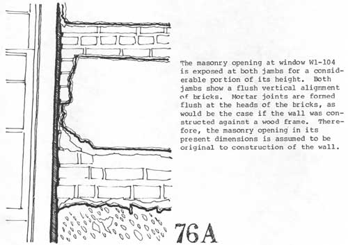
76 North wall RM 104, east jamb at window W1-104.
|
|
|
76A
|
|
|
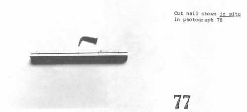
77 Cut nail shown in situ in photograph 78.
|
|
|
77A
|
|
|
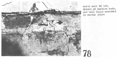
78 North wall RM 104, detail of machine made,
cut nail found embedded in mortar joint.
|
|
|
78A
|
|
|
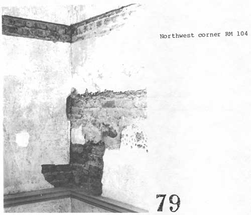
79 Northwest corner RM 104.
|
|
|
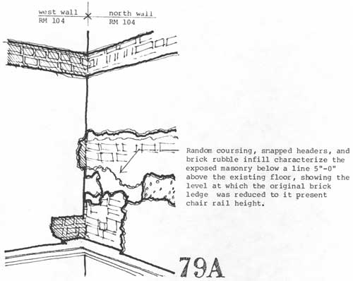
79A
|
|
|
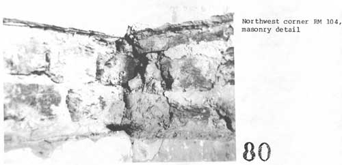
80 Northwest corner RM 104, masonry detail.
|
|
|
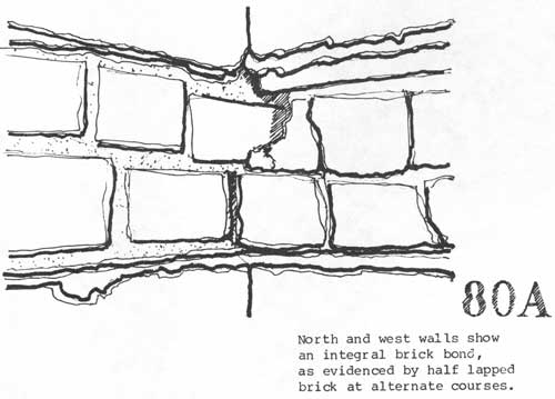
80A
|
III. SUMMARY OF FINDINGS
The evidence detailed in the preceding section
provides support for the theory that the north wing, while initially
constructed as a freestanding unit, was designed as an element in a
concept for the mansion as a whole. Bonded brick at three out of four
perimeter wall corners and continuity in construction indicate that the
shape and orientation of the existing structure is original. The window
openings in the east and north walls appear to have been constructed to
approximately their existing dimensions, although the first floor, at
its original height, spanned the middle of the openings. Apart from the
unexplained brick jambs on the east wall of Rm. 106, the absence of
infilled masonry openings relating in a more conventional manner to the
original floor level suggests that the north wing facade was designed to
fit the formal and aesthetic requirements of the completed mansion. Of
particular interest is the fact that no infilled openings were found on
the west wall. The absence of any openings original to construction of
this wall serves as circumstantial evidence of intent to add an
additional architectural element to that elevation (i.e., The Loggia).
The apparent conflict between exterior appearance and interior division
of space is consistent with the assumption that G.W.P. Custis built the
north wing (c. 1802) while still a bachelor, both as a residence and as
a place to store his collection of Washington artifacts.1 The
extant physical evidence relating to the original interior finishes
— chair rail, baseboard, and wallpaper — is diagnostic of
residential use. However, based on the physical evidence suggesting that
the north wing facade was intended to serve as an element in a larger
design concept, it seems probable that this arrangement was regarded as
an interim measure.
As finances permitted and the requirements of family
life dictated, Custis continued development of the design scheme. The
diary of artist William Birch recorded a visit to the Arlington House,
probably in September of 1805. He noted that Custis "Had built the two
wings of his Capital House."2 Custis' daughter, Mary Ann
Randolph Custis (b. 1808), related in a letter that the family lived in
the two wings of the house for a number of years before the central
block was completed.3 Unfortunately, no documentary source
has been located which refers to the interior arrangement of either of
the wings during this period. Although the location of several pre-floor
reduction partitions has been determined from the physical evidence,
there is insufficient information on which to base a complete interior
plan for the earliest construction period. Also, it is probable that at
least one major change in interior arrangement occurred prior to the
reduction in floor height.
Although no definitive date can be assigned to the
change in floor level on the basis of the available evidence, the first
major traces of a post floor reduction room arrangement cannot predate
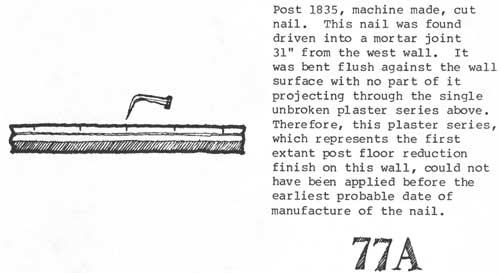
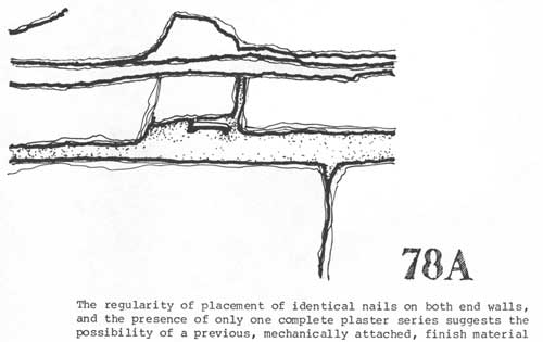
the post 1835 cut nails found driven into the brick of the north and
south perimeter walls. The principal extant feature of this phase is a
room at the north end of the wing, approximately 15'—6" x
22'—0", characterized by the cornice and neck molding shadows
presently visible in Rms. 104, 105, and 106. Again, the physical
evidence is insufficient to determine the dating of this arrangement or
its layout in the remainder of the wing.
The partition arrangement following this phase
represents the existing condition in the north wing. There is presently
no definitive means of establishing a date of construction for the
existing partitions. Because the partition/perimeter wall intersections
have been cut full height and patched over expanded metal lath, the
continuity of partition and perimeter wall plaster series cannot be
established. While it is possible that the present partition locations
represent the 1861 interpretive period condition, there is no compelling
evidence in support of this conclusion. The presence of post 1870
machine made lumber in door openings and the continuity of lath and
plaster adjacent to these openings provides circumstantial evidence that
the partitions themselves may post date the interpretive period.
1. Charles W. Snell. Historic Structures Report,
Historic Data Section, Vol. 1 (Unpublished Manuscript). March 1982. pp.
11-12.
2. IBID., p. 19.
3. IBID., p. 23.
4. IBID., p. 24.
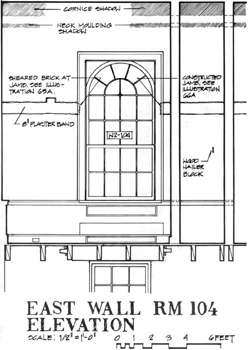
|
East Wall RM 104 Elevation
(click on image for a PDF version)
|
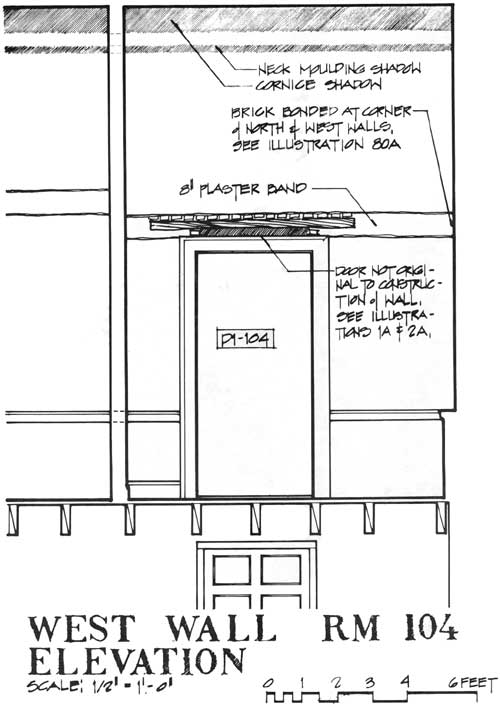
|
West Wall RM 104 Elevation
(click on image for a PDF version)
|
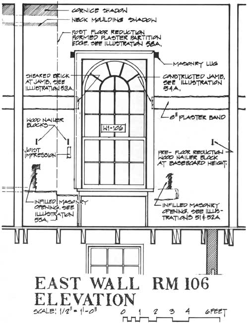
|
East Wall RM 106 Elevation
(click on image for a PDF version)
|
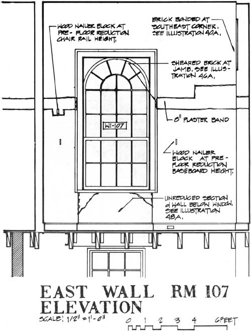
|
East Wall RM 107 Elevation
(click on image for a PDF version)
|
|
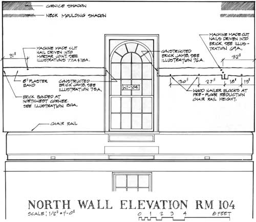
North Wall Elevation RM 104
(click on image for a PDF version)
|
|
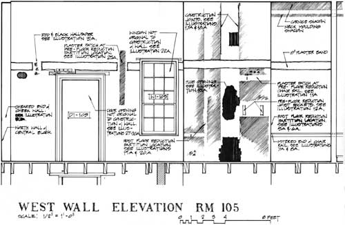
West Wall Elevation RM 105
(click on image for a PDF version)
|
|
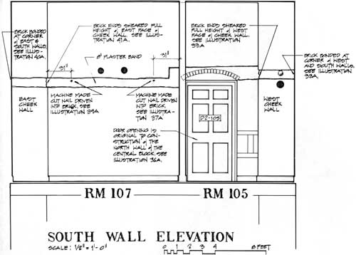
South Wall Elevation
(click on image for a PDF version)
|
|
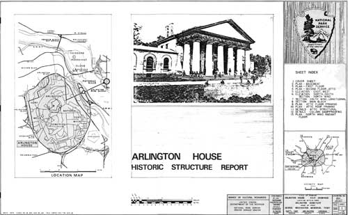
Arlington House
(click on image for a PDF version)
|
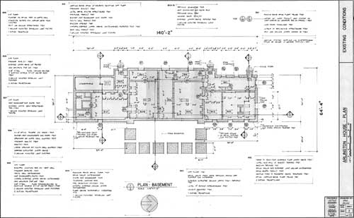
|
Arlington House Plan — Existing Conditions
(click on image for a PDF version)
|
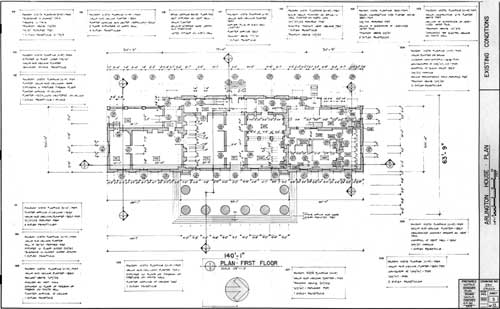
|
Arlington House Plan — Existing Conditions
(click on image for a PDF version)
|
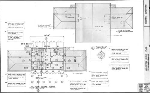
|
Arlington House Plan — Existing Conditions
(click on image for a PDF version)
|
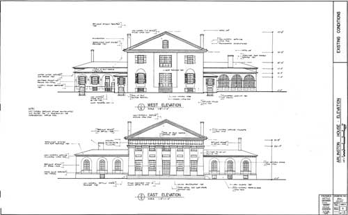
|
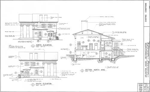
Arlington House Elevation — Existing Conditions
(click on image for a PDF version)
|
|
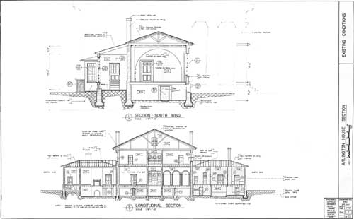
Arlington House Section-Elevation — Existing Conditions
(click on image for a PDF version)
|
|
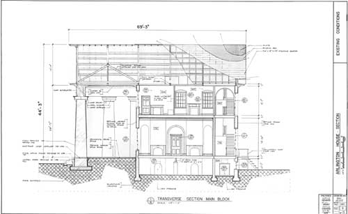
Arlington House Section — Existing Conditions
(click on image for a PDF version)
|
|
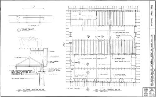
Arlington House Section — Existing Conditions
(click on image for a PDF version)
|
|
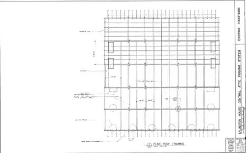
Arlington House Central Attic Framing System — Existing Conditions
(click on image for a PDF version)
|
|
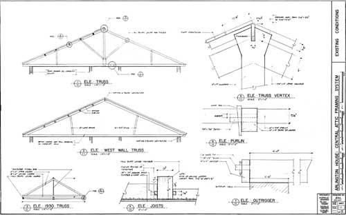
Arlington House Central Attic Framing System — Existing Conditions
(click on image for a PDF version)
|
|
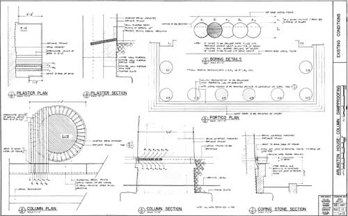
Arlington House Central Attic Framing System — Existing Conditions
(click on image for a PDF version)
|
|
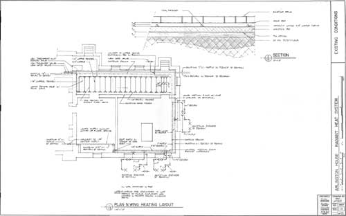
Arlington House Column Dampproofing — Existing Conditions
(click on image for a PDF version)
|
|
Arlington House Radiant Heat System — Existing Conditions
(click on image for a PDF version)
|
hsr1-phase2/app6.htm
Last Updated: 05-July-2011
|


